Rockwell Automation Flex/WebPak 3000 DC Drive Inverting Fault CB Kit 1.5-30HP-230VAC, 3-60HP-460VAC User Manual
Page 5
Inverting Fault Circuit Breaker Kit for FlexPak 3000 and WebPak 3000 Drives
5
Step 3. Connect the motor armature lead marked A2 to the drive motor terminal block (see Figure 3 for
location). If the motor has a series field, connect motor lead A2 to motor lead S1, and connect the
motor lead S2 to the drive motor terminal block marked 45.
Removing and Replacing Fuse 11FU
Step 1. Remove the drive’s front cover, then open the regulator carrier and remove the armature fuse plastic
cover over the armature fuse (11FU). Refer the drawing on the back of the carrier for the location of
11FU.
Step 2. Remove the hardware used to attach 11FU to the drive.
Step 3. Replace 11FU with the jumper/bar (part number 610273-30RN, 610273-101A, or 610273-102A)
provided with the kit. Use the hardware removed from 11FU to install the jumper/bar in place of 11FU.
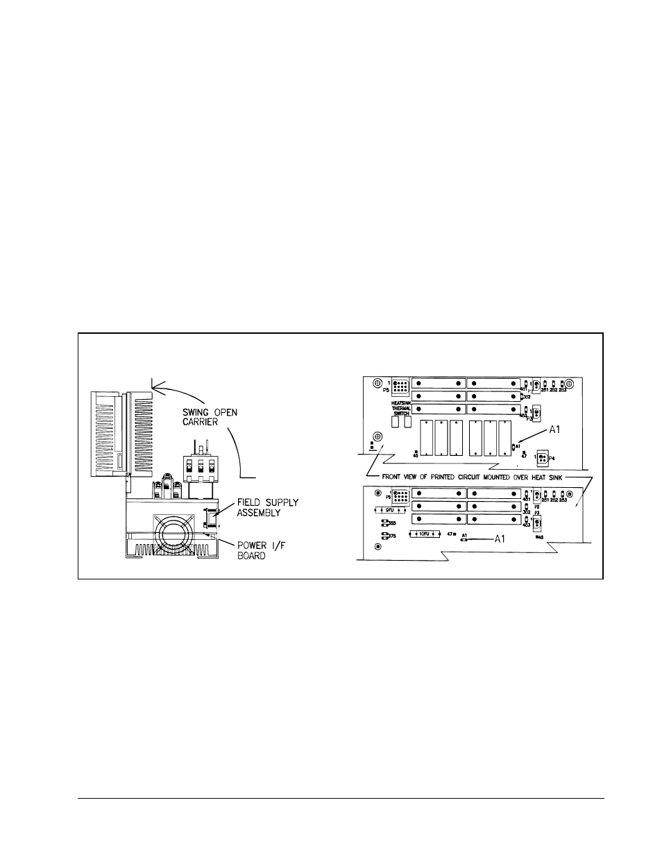
Connecting the Wire Assembly
Step 1. Locate and remove the jumper wire from the 11FU terminal marked A1 and the terminal marked A1
on the Power Interface board. See Figure 4 for the location of the Power Interface board and terminal
A1 on the Power Interface board.
Step 2. Attach the spade connector on wire harness part number 610273-68R to the A1 terminal on the
Power Interface board. Route the other end of this wire to the inverting fault circuit breaker terminal
marked A1. Cut the wire to length as required and then terminate the end with the ring lug (part
number 68321-19D). Connect the ring lug to the A1 terminal on the inverting fault circuit breaker.
Step 3. Connect the spade connectors of the twisted pair harness (part number 610273-68S) to the male
connectors coming out of the side of the inverting fault circuit breaker. Route this harness down to the
bottom of the drive and connect it to terminals 9 and 11 on the regulator control terminal strip. See
Figure 5.
Important: If any other interlocks are required for your application, they must be connected in series to the
Customer Interlock Input (terminals 9 and 11) along with the circuit breaker.
Figure 4 – Power Interface Board and Terminal A1 Locations