Install cables – Rockwell Automation 2090-CPxxx Standard Power Cables with SpeedTec DIN Connector Type 923 User Manual
Page 4
4 Standard Power Cables with SpeedTec DIN Connector Type 923
Publication 2090-IN022A-EN-P - September 2010
Install Cables
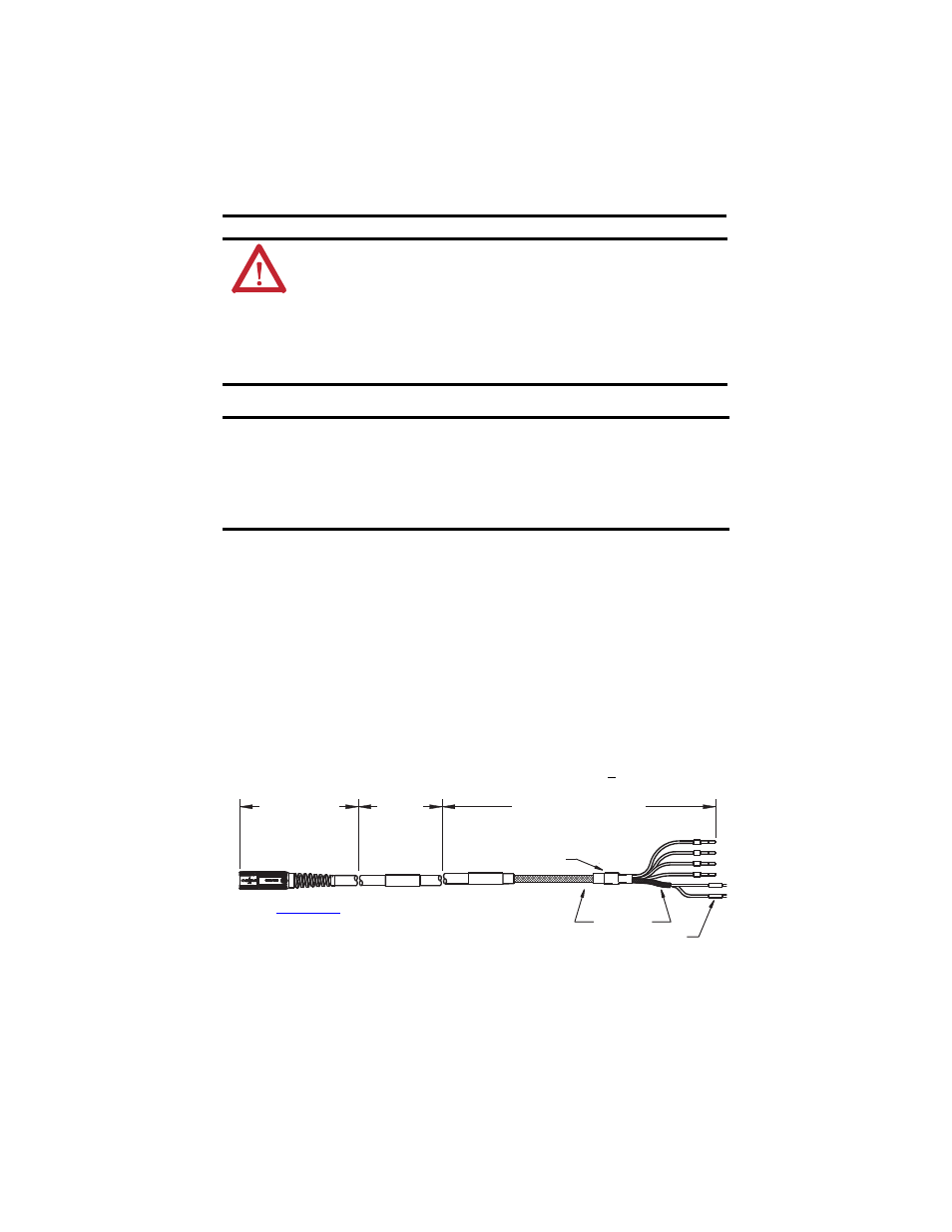
Follow these steps when installing a cable.
1.
Identify the recommended installation areas and the correct offset from features before
beginning any cable bend. Features include these areas on the cable:
•
Connectors
•
Transitions from exposed wire to insulation (for example, flying leads)
•
Exposed cable ground shields
The offset from these features should be greater than or equal to (>1x) the cable
diameter.
ATTENTION: The examples in this publication show all the available
connections, some of which may not be appropriate for your specific
installation. Refer to your drive installation or user manual for recommended
wire trim lengths, and wiring examples appropriate to your drive and motor
application.
Do not connect unused wires. Unused wires may be trimmed and finished as
necessary to prevent accidental contact with other wires or wire shields, or with
a ground connection.
IMPORTANT
Motors equipped with SpeedTec-ready DIN connectors are fully compatible with
threaded (M4) cable plugs. SpeedTec-ready DIN motor connectors are also
compatible with SpeedTec (M7/E7) cable plugs when the o-ring on the motor
connector is removed.
Motors equipped with threaded DIN (M4) connectors are compatible only with
threaded (M4) cable plugs.
U
PE
V
W
MBRK+
MBRK-
Limited
Bend Zone
Installation
Area
Installation
Area
Label
(6 Places)
Exposed
Shields
Shrink Wrap
for recommended
Installation Area and Bend Zone values.