Install the control interface breakout board – Rockwell Automation 2090-U3BB-DM12 CN1 Control Interface Breakout Boards Installation Instructions User Manual
Page 2
2 Control Interface Breakout Boards
Rockwell Automation Publication 2090-IN007D-EN-P - August 2010
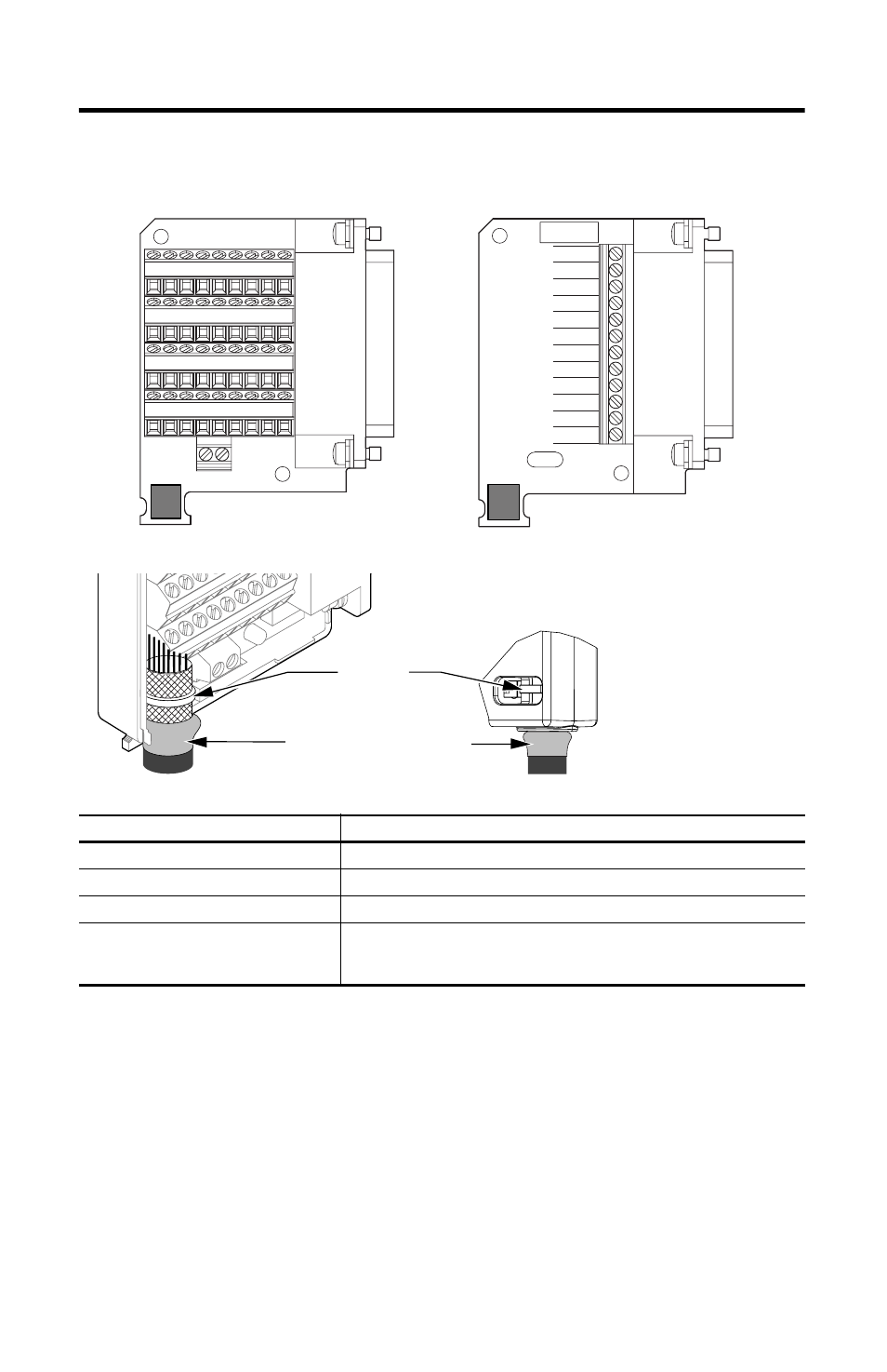
Install the Control Interface Breakout Board
Attribute
2090-U3BB2-DM44, 2090-U3BB-DM12
Cable diameter
12.7 mm (0.5 in.) max
Screw terminal wire size
0.06…1.31 mm
2
(30…16 AWG)
Recommended wire strip length
25…63 mm (1.0…2.5 in.)
Recommended torque
Mounting screws
Terminal screws
0.40 N•m (3.5 lb•in)
0.25 N•m (2.2 lb•in)
1 X- X+ 4 5 6 7 8 9
16 17 18 19 20 21 22 23 24
25 26 27 29 31 32 33 34 35
36 37 38 39 40 41 42 43 44
CN1-3
CN1-2
CN1-31
CN1-32
CN1-33
CN1-34
CN1-37
CN1-38
CN1-27
CN1-43
CN1-44
SHIELD
5V AUX
Cable Tie
Follow these steps to form a compact connection.
1. Push the insulation down-and-over itself.
2. Move the insulation so it butts against the outside wall of
cover.
3. Tape or shrink-wrap the end of the insulation to the cable.
Shrink-wrapped Insulation
44-pin Breakout Board
12-pin Breakout Board