Figure 5. outline dimensions, Figure 7 accessories, Figure 8 – Rockwell Automation 5100 Background Suppression Control Type 42MBS User Manual
Page 3
3
NOTE:
1. The operating margin in parenthesis are for diffuse white sur-
faces that fill the control’s field of view.
2. 6.1% and 2.6% designate dark colored surfaces having diffuse
reflectance of 6.1% and 2.6% respectively compared to diffuse
white.
3. The 2.6% surface is Krylon #1602 ultra flat black.
APPLICATION PRECAUTIONS
In a background suppression control the high sensitivity and
sharp
cut off are obtained by using two Photodetectors. The Object
detector senses in close while the background detector senses further
out.
As long as the background detector signal is greater than or equal
to the object detector signal, the control remains “OFF.” When the
object detector signal becomes greater than the background detector
signal, the control turns “ON.”
This comparing of the two detector signals and the partially over-
lapping sensing areas requires that the object being sensed travels
through both sensing areas at the same time and not through one
sensing area before reaching the other sensing area or false operation
will occur. Therefore an object always should travel on an
X axis
perpendicular with the control. See Figure 5 and 6.
Direction
of travel
Suppression
point
OBJECT
TO BE
SENSED
FIELD
OF VIEW
OVERLAP
FAR SENSING
AREA
CLOSE IN SENSING
AREA
FIGURE 5
WRONG Directions of Travel. The object is not in the field of view
of both photodetectors at the same time. See Figure 6.
Direction
of travel
Suppression
Point
Control
Top View
Both
sensing areas
overlap
OBJECT
TO BE
SENSED
FIGURE 6
CORRECT Directions of Travel, Rotated Control 90 from
Figure 5.
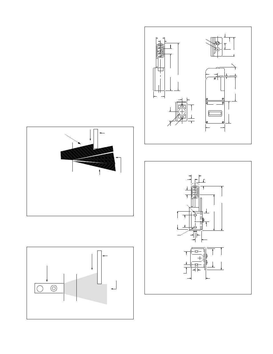
OUTLINE DIMENSIONS
(15.4)
39/64
(11.9)
15/32
(24.2)
61/64
(139.5)
5 33/64
(106.5)
4 1/4
2 HOLES
10--32 UNF
NPSM
1/2--14
(27.3)
1 5/64
(8.3)
21/64
(38.1)
1 1/2
(13.8)
35/64
(54.7)
2 5/32
(65.8)
2 19/32
(71.0)
2 51/64
(2.7)
7/64
(8.7)MIN.
1 1/32
(36.5)
1 17/16
TO REMOVE SCANNER
LED
INDICATOR
QUICK DISCONNECT
SCREW
(54.7)
2 5/32
(36.5)
17/16
(19.4)
49/64
1 5/16
(33.3)
FIGURE 7
ACCESSORIES
11/32
(8.73)
61/64
(24.2)
15/32
(11.9)
39/64
(15.4)
Control with Terminal Base
1
(25.4)
5 24/32
(146.4)
4 11/32
(110.3)
2 1/2
(63.5)
1 1/4
(31.7)
#10 32
THREAD
2 HOLES
59/64
(23.4)
1/4
(6.3)
CLEARANCE
FOR
#10 32
HDW
2 1/2
(63.5)
1 1/2
(38.1)
1/4 (6.3)
1 14/32
(61.9)
21/64
(8.3)
2 5/32
(54.7)
HEAVY DUTY MOUNTING ASSEMLY
#60 1748
FIGURE 8