Rockwell Automation 5100 Background Suppression Control Type 42MBS User Manual
Rockwell Automation Equipment
INSTALLATION INSTRUCTIONS
PHOTOSWITCH BACKGROUND SUPPRESSION
CONTROL TYPE 42MBS SERIES 5100
IMPORTANT: SAVE THESE INSTRUCTIONS FOR FUTURE USE. FOR ADDITIONAL INFORMATION, REFER TO PUBLICATION P
A 8921
SPECIFICATIONS
Voltage Supply
Type
42MTB 5000
102 132VAC, 50/60Hz
. . . . . . . . . . . . .
Type
42MTB 5001
204 264VAC, 50/60Hz
. . . . . . . . . . . . .
Type
42MTB 5002
40 54VAC, 50/50Hz
. . . . . . . . . . . . . . .
40 54VDC
Type
42MTB 5003
20 30VAC, 50/60Hz
. . . . . . . . . . . . . . .
Type
42MTB 5004
20 30VDC
. . . . . . . . . . . . . . . . . . . . . . .
Power Consumption
2VA @ 120VAC,
. . . . . . . . . . . . . . . . . . . .
4VA @ 240VAC
1VA @ 24/48VAC
Response Time
Type 42MBS -- 5ms
. . . . . . . . . . . . . . . . . . . . . .
with EM Relay
#8 590,
#8 594
Operate 10ms additional
. . .
Release 15ms additional
with FET Relay
#8 591
1ms additional
. . . . . . . . . . . . . . . . .
with Triac Relay
#8 592
8ms additional
. . . . . . . . . . . . . . . .
with dual Source/Sink
#8 593
1ms additional
. . . . . . . . . . . .
Light/Dark Energized option
Yes
. . . . . . . . . . . . . . . . . . . . . . .
Turn on Pulse Suppression
Yes
. . . . . . . . . . . . . . . . . . . . . . . . .
Gain Margin and Alignment Indicators
Red
Output Energized
. . . . . . . . . . . . . . . . . . . . . . . . . . . . . . .
Green
2X margin
. . . . . . . . . . . . . . . . . . . . . . . . . . . . . . . . . . .
Field of View
3
o
. . . . . . . . . . . . . . . . . . . . . . . . . . . . . . . . . . . . . .
Suppression Point Adjustment Range
2.5
”--12”
. . . . . . . . . . . .
(6.3--30.5cm)
SUPPRESSION QUALITY SPECIFICATIONS
(Based on Operating Margin of 20)
White Background (Unit Off)
Black Target (Unit On)
2.5
” (6.35cm)
2.3
” (5.84cm)
4
” (10.1cm)
3.9
” (9.9cm)
6
” (15.2cm)
5.8
” (14.7cm)
8
” (20.3cm)
7.7
” (19.5cm)
10
” (25.4cm)
9.5
” (24.1cm)
12
” (30.5cm)
10.5
” (26.6cm)
Timing Ranges
Short
Long
Two Way Time Delay (ON & OFF Delays
0 1.5 sec.
0 15 sec.
ON Delay
0 1.5 sec.
0 15 sec.
OFF Delay
0 1.5 sec.
0 15 sec.
One Shot
0 1.5 sec
0 15 sec.
Delayed One Shot
0 1.5 sec
0 15 sec.
Transmitting LED
Infrared 880nm
. . . . . . . . . . . . . . . . . . . . . . .
Lens Material
Acrylic with protective hard coating
. . . . . . . . . .
Housing Material
High Impact, chemically resistant Valox
. . . .
Operating Environment:
NEMA 3, 4, 12, 13 and IP66 (IEC144) rated housing
Ambient Temperature
--40
F to 150
F
. . . . . . . . . . . . . . . . . . . .
--40
C to 65
C
Relative Humidity
90%
. . . . . . . . . . . . . . . . . . . . . . . . . . . . . . . .
Terminal Base
Supplied with
#6 32 nickel plated
. . . . . . . . . . .
brass pressure type terminal.
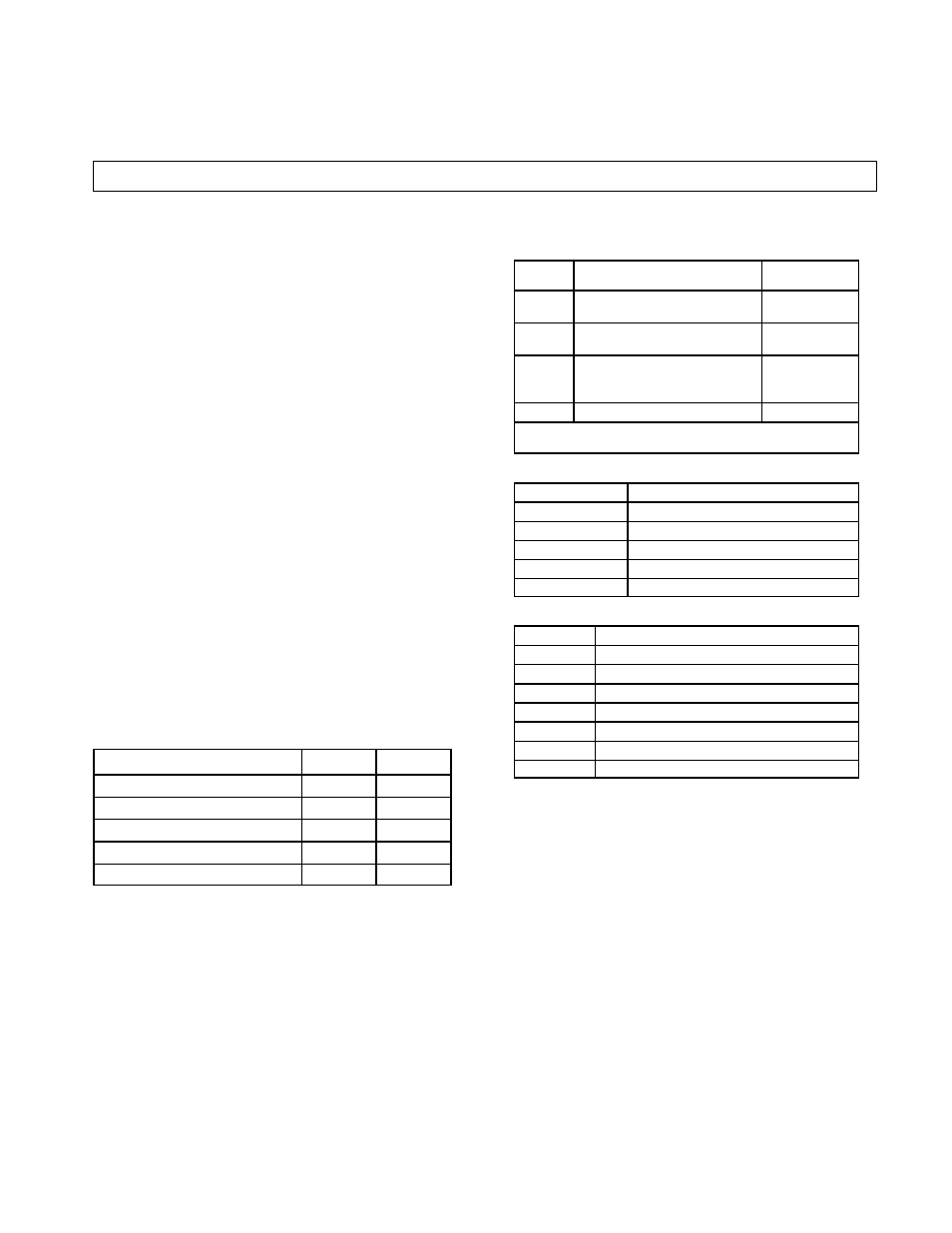
ORDERING INSTRUCTIONS
1. Order Type 42MBS Model 5100 Photohead.
2. Select output.
PART
NUMBER
TYPE
RATING
8 590 &
8 594*
(SPDT) EM--RELAY
2A, 120 VAC
1A, 240VAC
8--591
(SP NO) FET SS--RELAY
30mA CONT.
0 120VAC/DC
8--592
(SP NO) AC POWER TRIAC
SS RELAY
.75A CONT.
10A SURGE
24--240VAC
8 593*
NPN & PNP SINK/SOURCE
100mA AT 30VDC
* Use with 42MTB--5004 base only. Other output modules will not func-
tion with 5004 base.
3. Select power base.
VOLTAGE SUPPLY
TYPE AND MODEL
120VAC
42MTB- 5000
240VAC
42MTB- 5001
48VAC/DC
42MTB- 5002
24VAC
42MTB- 5003
24VDC
42MTB- 5004
4. Select optional mounting accessories.
PART NUMBER
DESCRIPTION
60- 1785
Universal Mounting Assembly 360
o
Adj.
60- 1748
Heavy--Duty Mounting Assembly
60 2014
Flexi Mount Mounting Assembly
60- 2072
Photocount Switch Totalizer
60- 2083
Photoguard Heavy Duty Protection
60- 2213
Conduit Mounting Adaptor
60- 2230
Limit Switch Type Mounting Assembly
INSTALLATION
The control must be securely mounted on a firm, stable surface
or support. A mounting which is subject to excessive vibration or
shifting may cause intermittent operation. For installation conve-
nience, Heavy Duty Mounting Assembly
#60 1748, or Universal
Mounting Assembly
#60 1785, is recommended. For excessive vi-
bration environments, use Solid State Relay outputs.
Wiring:
It is recommended that
Plug In Output devices be inserted prior
to wiring to the terminals. Also, sufficient “loop” should be provided
for wiring connections to terminals in order to facilitate insertion or
removal of the
Plug In Output device.
All external wiring should conform to the National Electrical
Code and applicable local codes. See Wiring Diagram for electrical
connections (page 2).