Install the low-profile connector kit – Rockwell Automation 2094-K6CK-D44M Low-profile Connector Kit for I/O, Safety, and Auxiliary Feedback User Manual
Page 2
2 Low-profile Connector Kit for I/O, Safety, and Auxiliary Feedback Signals
Rockwell Automation Publication 2090-IN021C-EN-P - July 2013
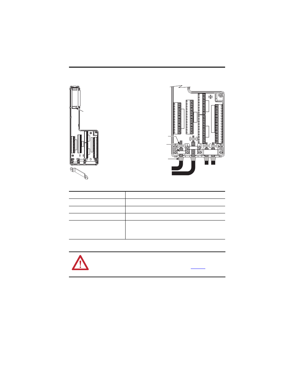
Install the Low-profile Connector Kit
Attribute
2090-K6CK-D44M
Cable diameter
4…10 mm (0.16…0.39 in.)
Screw terminal wire size
0.06…1.31 mm
2
(30…16 AWG)
Recommended wire strip length
5 mm (0.2 in.) single conductor
Recommended torque
Mounting screw
Terminal screws
Clamp and cover screws
0.4 N•m (3.5 lb•in)
0.2 N•m (2.1 lb•in)
0.4 N•m (3.5 lb•in)
ATTENTION: This connector kit contains electrostatic discharge (ESD) sensitive parts that can be
damaged if you do not follow ESD control procedures. If you are unfamiliar with ESD control
procedures, refer to Guarding Against Electrostatic Damage, publication
other
applicable ESD protection handbook.
28 27 26 25 24 23 22 21 20 19 18 17 15 14 0
AUX FEEDBACK
0 11 10 9 8 7 6 5 4 3 2 1
0 39 41 40 39 42 40 39 43 40 39 44 40
INPUTS
0 38 37 36 35 34 33 32 31 30 29
28 27 28 27 28 27 28 27
S1 ONL
Y
S1 ONL
Y
S0&S1 W/S0 DISABLED
28 27 26 25 24 23 22 21 20 19 18 17 15 14 0
AUX FEEDBACK
0 11 10 9 8 7 6 5 4 3 2 1
0 39 41 40 39 42 40 39 43 40 39 44 40
INPUTS
0 38 37 36 35 34 33 32 31 30 29
28 27 28 27 28 27 28 27
S1 ONL
Y
S1 ONL
Y
S0&S1 W/S0 DISABLED
Follow these steps to form a compact connection.
1. Push the insulation down-and-over itself.
2. Move the insulation so it butts against the
outside wall of cover.
3. Tape or shrink-wrap the end of the insulation
to the cable.
Mounting
Screw (2)
If necessary, turn clamp over to hold
small wires secure.
Shrink-wrapped Insulation
Use shield clamps (3) to maximize contact with
cable shield for high-frequency bonding.
Use tie wraps (4) for stress relief.
Aux. Feedback and
I/O Wires and Cables
Safety Wires
and Cables