Connecting the type b cable – Rockwell Automation 2711 PanelView 550/900 Profibus Communications User Guide User Manual
Page 10
PROFIBUS DP Communications
10
Publication 2711-6.3
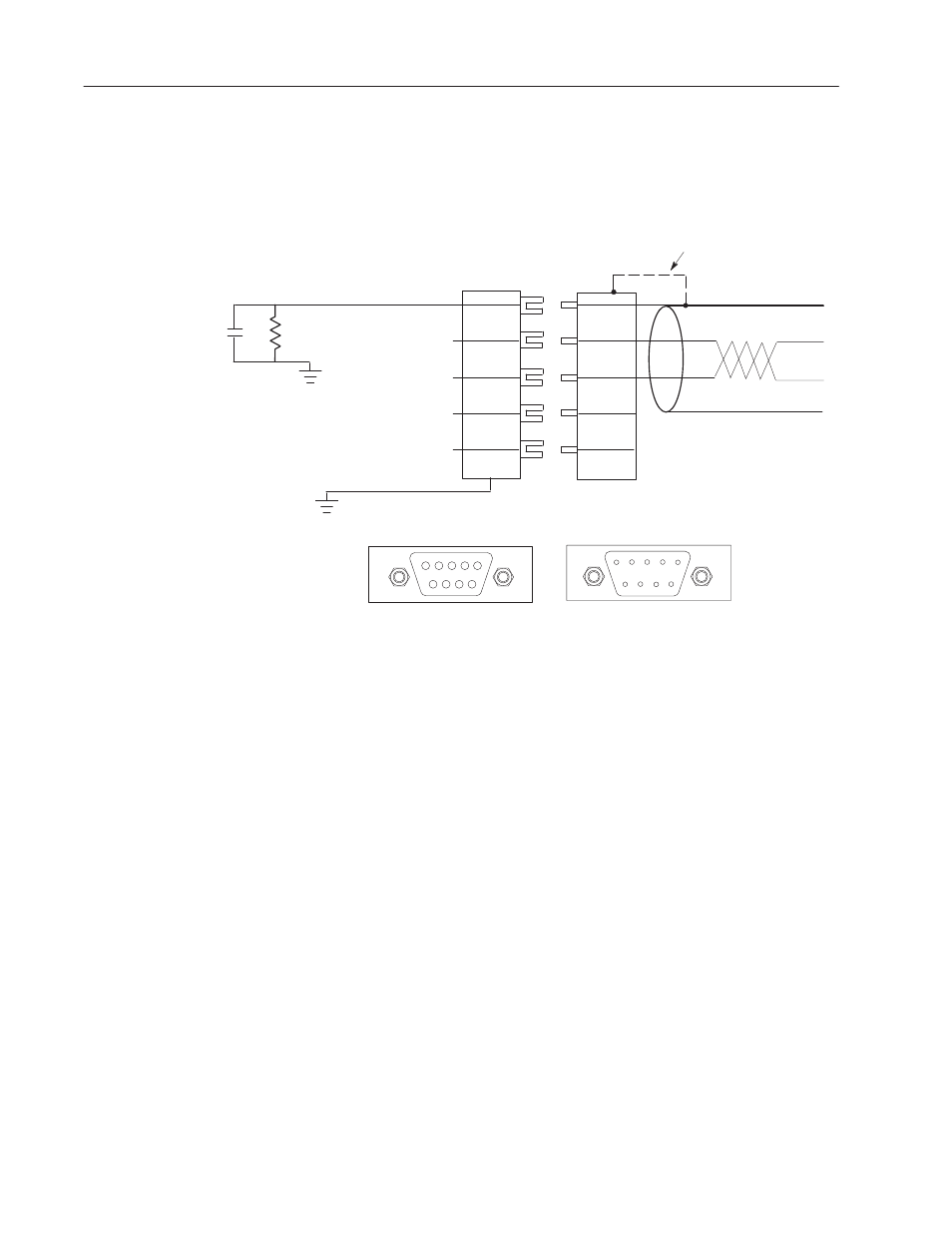
Connecting the Type B Cable
The following diagram shows how the Type B cable connects to the
PanelView.
Pin #1
Pin #3
Receive/Transmit +
Pin #8
Receive/Transmit –
Pin #5
Data Ground
Pin #6
+5 V
Receive/Transmit +
Receive/Transmit –
PanelView
PROFIBUS DP Connector
PROFIBUS DP Cable
Connector
PROFIBUS Cable
5
1
9
6
Cable Connector
1
5
6
9
PanelView Connector
Pin #1
! Cable Shield
Pin #3
! Receive / Transmit Data Positive
Pin #8
! Receive / Transmit Data Negative
Pin #5
! Data Ground
Pin #6
! +5V
0.01
mF
1M
W
Shield Drain Wire
(Connected to chassis ground
through connector shroud.
Internal Circuit
Note: Connect the cable shield to Pin 1 of the connector. For
compliance with European Electromagnetic Compatibility (EMC)
directives, also connect the cable shield to the metal shroud of the
connector on both sides of the connection.. This connects the cable
shield to chassis ground through the connector shroud and bypasses
the R/C filter.
Important: For improved noise immunity in long distance
networks, an alternate wiring connection may be preferred to avoid
dc and low frequency ground loops. In such cases, connect the cable
shield directly to the local chassis ground (through connector shroud)
at only one point on a PROFIBUS DP network.