Rockwell Automation 7000 PowerFlex Medium Voltage Air-Cooled (B Frame) Installation - ForGe Control User Manual
Page 40
40
Rockwell Automation Publication 7000-IN007E-EN-P - June 2014
Chapter 3
Drive Installation
Even if the shock indicators are clear, perform a full equipment inspection and
verification. Refer to
Pre-Commissioning Responsibilities on page 65
for details
on the inspection and verification process.
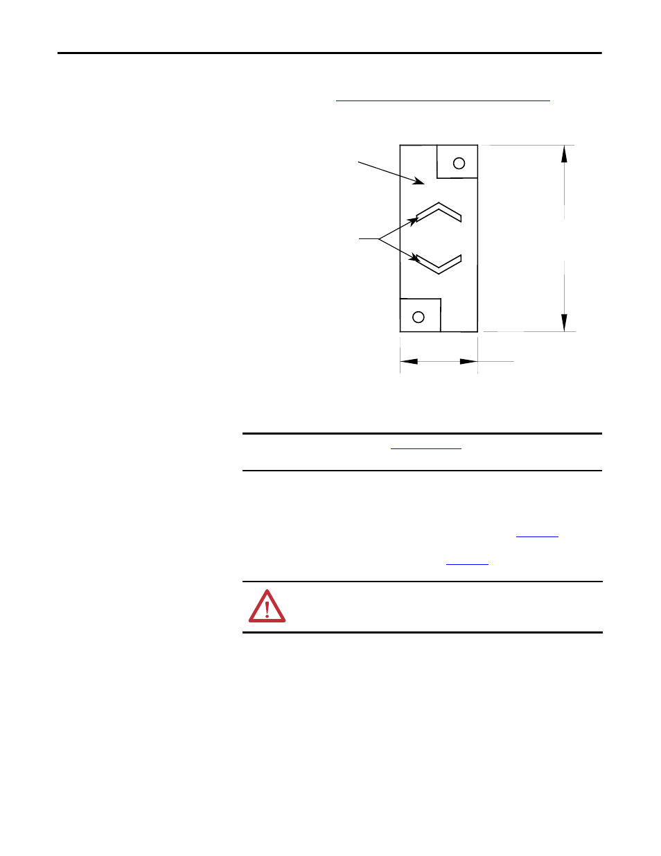
Figure 31 - Shock Indicator
Joining Shipping Splits
(3300...4160V and 6600V
Heat Pipe Model)
The 3300...4160 and 6600V heat pipe drives are the “B” Frame models that ship
in multiple sections (two for 3300...4160V and three for 6600V). All other “B”
Frame models ship as a single unit. For the 3300...4160V heat pipe model, the
choke section ships separately from main section of the drive (
). For the
6600V heat pipe model, the choke cabinet and the line reactor section ship
separately from the main section of the drive (
)
Arrange the sections as directed in the dimension drawings and move the sections
together. Join the enclosure’s side sheets with thread-forming screws using the
available holes.
Complete ground bus, power, and control connections as directed in the
electrical diagrams and this installation guide.
Red Plastic Housing
Window Area appears black
if subjected to shock
51 mm
(2.0)
21 mm
(0.8)
IMPORTANT
Refer to publicat
details regarding moving and
siting the drive before continuing with these installation procedures.
ATTENTION: Install the drive on a level surface (+/- 1 mm over the length of
the drive). Use metal shims if necessary to level the cabinets before joining
them; attempting to level after joining may result in twisting the cabinets.