Rockwell Automation 2090-CHBIFS8-12AA Kinetix 6000M IPIM to IDM Hybrid Power Cable Installation Instructions User Manual
Page 4
4 Kinetix 6000M IPIM-to-IDM Hybrid Cable
Publication 2090-IN031B-EN-P - March 2012
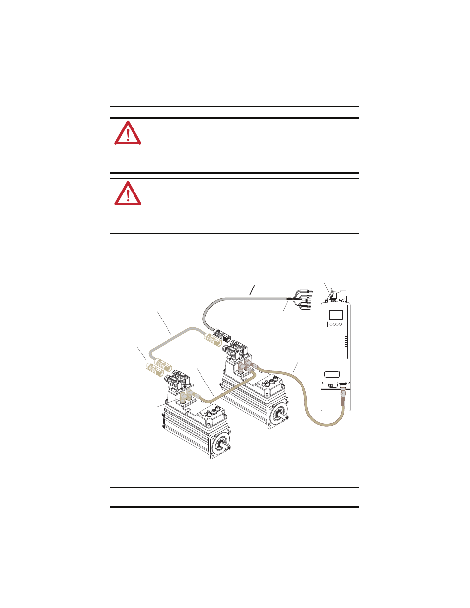
Kinetix 6000M Cable Routing Diagram
ATTENTION: The examples in this publication show the available connections, some of which may
not be appropriate for your specific installation. Refer to your system level installation instructions
or user manual for recommended wire trim lengths, and wiring examples appropriate to your
application.
Failure to observe these safety procedures could result in personal injury or damage to the motor
and equipment.
ATTENTION: Do not tightly gather or coil the excess length of a hybrid cable. Heat is generated
within a cable whenever power is applied. Always position a hybrid cable to freely dissipate heat.
A hybrid cable should not be coiled, except for temporary use when building or testing a machine.
If you temporarily coil a hybrid cable, you must also derate the cable to meet local code or follow
an authoritative directive, such as Engineering Section 310.15(C) of the NEC Handbook.
Failure to observe these safety procedures could result in personal injury or equipment damage.
IMPORTANT
The colored rings on the hybrid cable connector and the mating cable must match: red-to-red
or green-to-green.
PORT 1
PORT 2
NETWORK
R
R
G
G
R
R
G
G
2094-SEPM-B24-S
IPIM Module
2090-CHBIFS8-12AA
xx
IPIM-to-IDM Hybrid Cable
Connects the IPIM Module to the First IDM Unit
2090-CHBP8S8-12AA
x
Hybrid Cable
2090-CTHP8
Hybrid Terminator
2090-CNSRPRS xx
Network Cable
MDF-SB1
xxx
Last IDM Unit
2090-CTSRP
Network Terminator
2090-CNSSPRS xx
Network Cable
MDF-SB1
xxx
First IDM Unit
Ground
Clamp
Exposed
Shield