Rockwell Automation 61C365 4 Output 4-20mA Analog Rail User Manual
Page 29
4Ć7
4.1.2
AutoMate Programming in Rail Mode
In Rail mode, the Analog Rail module is imaged in one I/O register of
the processor. Data from one of the four channels will occupy the
register as a function of the channel select bits. The active channel
is updated at the end of each scan. For the output channels, the
data in the register must be in the format shown in figure 4.6 prior to
the I/O update.
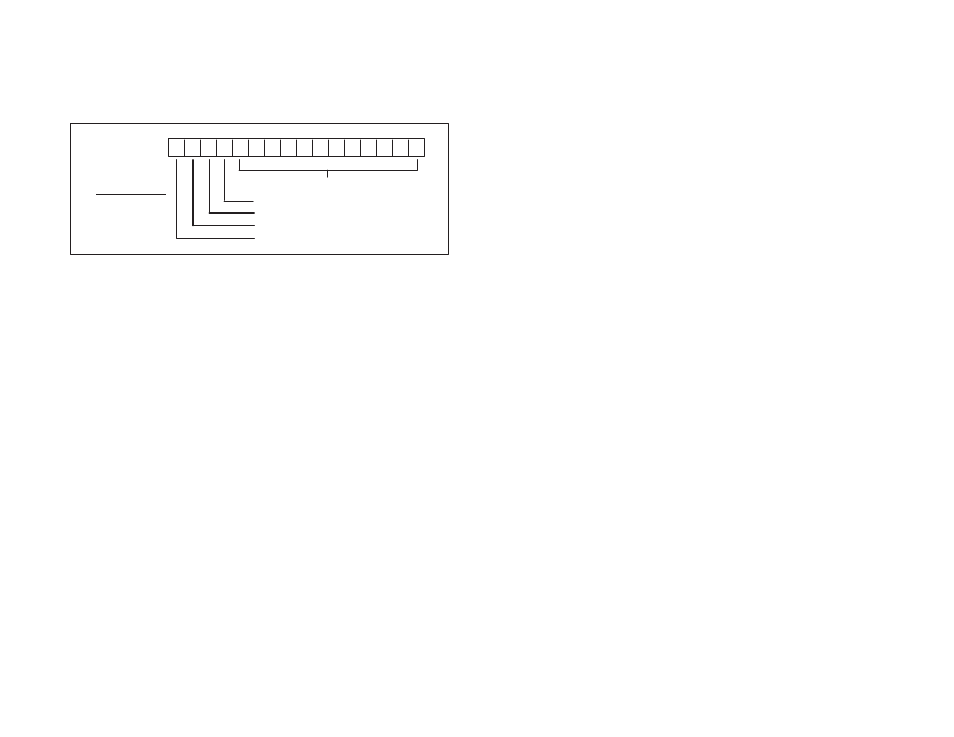
17 16 15 14 13 12 11 10 7 6 5 4 3 2 1 0
Octal
12 bits of analog output data
not used
not used
channel being modified: LSB
channel being modified: MSB
MSB LSB ăCH#
ă0ąą0 = CH 0
ă0ąą1 = CH 1
ă1ąą0 = CH 2
ă1ąą1 = CH 3
Figure 4.6 Ć Rail Mode Register Image for Output Channels
The Analog Rail module data may also be accessed in the middle of
the scan (as opposed to the end of the scan, which is the normal
mode of operation for digital rail I/O) using the appropriate number
of Analog Out (AOUT) blocks. The AOUT block will set the channel
select bits appropriately. See section 4.1.4 for more information
about the AOUT block.
Note that the AOUT block is supported for the AutoMate 20E
M/N 45C224 and 45C225, but not the AutoMate 20 (M/N 45C20,
45C21, 45C220, 45C221) by APX Version 3.0.
For processors that do not support the AOUT block, you can use
the MOVE block to move data in and out of the registers assigned
and to determine the channel select bits. The I/O update will occur
automatically at the end of each scan. See Appendix C for a sample
AutoMate program that writes to the Analog Rail module without
using AOUT blocks.