1,800 watt continuous dissipation cabinet layout – Rockwell Automation 2090-UCSR-P900 900 Watt Passive Shunt Module Installation User Manual
Page 5
Publication 2090-IN001A-EN-P — March 2001
900 Watt Passive Shunt Module 5
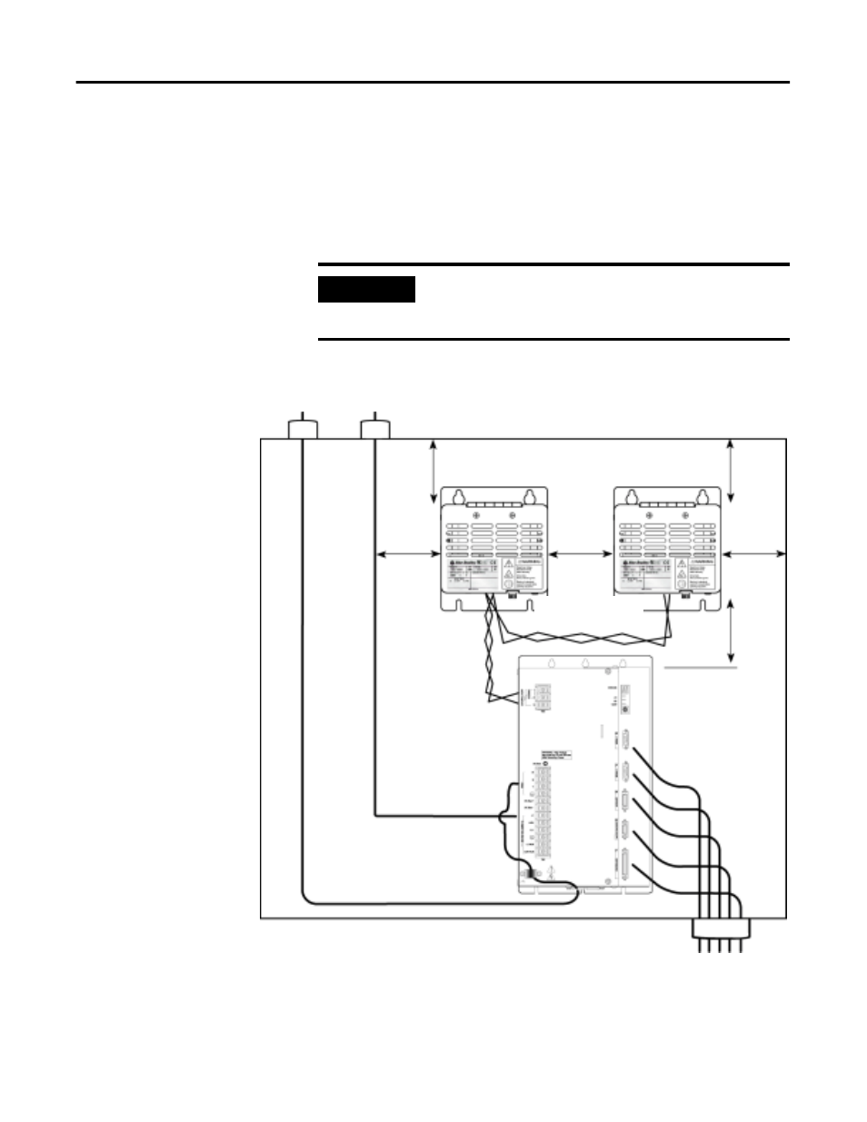
1,800 Watt Continuous Dissipation Cabinet Layout
Figure 3 details the proper position and cable separation for mounting
two shunt modules with one drive inside a cabinet. Two 900W shunt
modules are connected in a parallel, which doubles, to a total of
1,800W, the amount of continuous power dissipation on the DC bus.
Figure 3
Typical Shunt Module Position and Conductor Routing for 1,800W Continuous
Dissipation
IMPORTANT
No more than two passive shunt modules can be
used per DDM/DSD/IPD-150, PDM-150B or damage
to the drive will result.
AC power cables
155 mm (6.1 in.) of minimum clearance
on all sides of the shunt module
Always separate low
voltage signal wiring
from high voltage
power wiring to reduce
affects of EMI
When shielding is used, the
shield must be grounded to the
shunt and drive as is the motor
power cable
Motor power cables
Shielded metal
conduit, shielded
cable, and ferrite
filters are also
recommended for
reducing the effects
of EMI
Twist conductors
(2 twists per foot min.)