Rockwell Automation 9000 Series 9000 Intrinsically Safe Photoelectric Sensors User Manual
Page 2
2
2
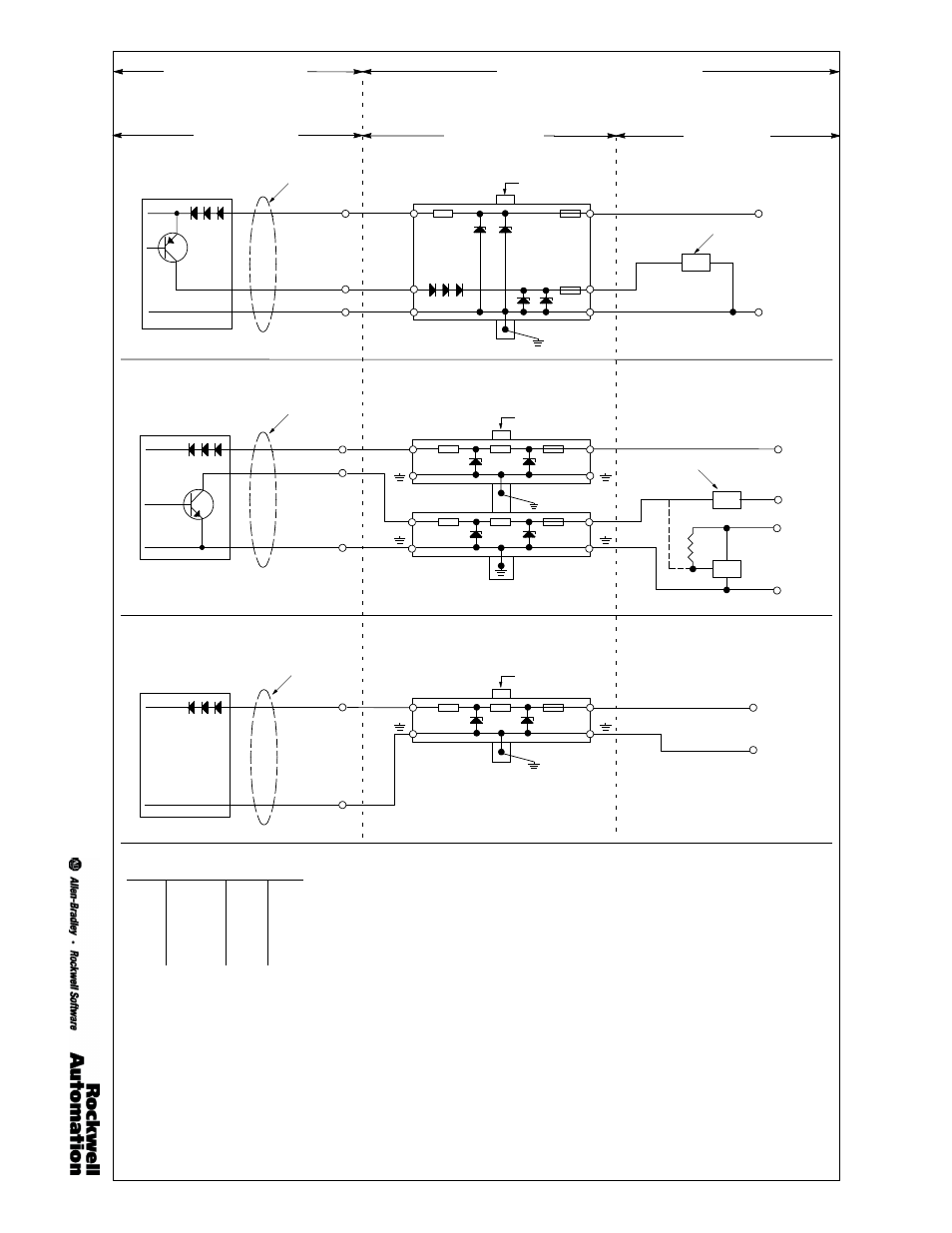
Receiver Model Numbers:
42GRR--9500, 42GRR--9500--QD, 42GRR--9500--QD1
Hazardous (Classified) Location
(See Note 1)
Hazardous (Classified) or Nonhazardous Loca-
tion
(See Note 2)
Photoelectric Sensors
Zener Diode Barriers
Power Supply &
Load Circuits
A--B #897H--S214
Cable
Brown (Pin 1)
(Pin 4)
Blue
(Pin 3)
Black
Receiver PNP Output Wiring
4
3
Barrier Bus
Power Supply
Sinking PLC Input
24V DC Nom.
( + )
Signal
Return
( -- )
Supply Return
8.5mA Max.
Earth Ground
(less than 1Ohm)
2
1
Receiver Model Numbers:
42GRR--9500, 42GRR--9500--QD, 42GRR--9500--QD1
A--B #897H--S150
A--B #897H--S150
Cable
Brown
Blue
White
(Pin 1)
(Pin 2)
(Pin 3)
3
3
Barrier Bus
Earth Ground
(less than 1Ohm)
1
1
Power Supply
Sourcing PLC Input
24V DC Nom.
( + )
Load
Supply
( -- )
Supply and Signal Return
15mA
Max.
24V DC Nom.
( + )
5V DC Nom.
( + )
TTL
Device
Receiver NPN Output Wiring
Light Source Model Numbers:
42GRL--9540, 42GRL--9540--QD, 42GRL--9540--QD1
A--B #897H--S120
Cable
Brown
Blue
(Pin 1)
(Pin 3)
3
Barrier Bus
Earth Ground
(less than 1Ohm)
1
Supply Return
Power Supply
24V DC Nom.
( + )
( -- )
Light Source Wiring
Table 1: Entity Parameters
Sensor
Barrier
Vmax
31.5V
≥
Vt
Imax
150mA
≥
It
Pmax
0.95W
≥
Pt
Ci
0F
≤
Ca
Li
0mH
≤
La
Notes
:
1. Class I; Division 1, Group A, B, C, D. Class I; Division 2, Group A, B, C, D.
2. Class I; Division 2, Group A, B, C, D if equipment and installation is per national standards.
3. Division 2 applications without the use of a barrier must be installed in accordance with the NEC and CEC.
4. Safety barriers are not required for Class I, Division 2 Group A, B, C, D non-incendive installations when installed per the CEC.
5. Entity parameters of Safety Barriers must match Table 1. Cable values for capacitance and inductance must be added to Ci and Li
values.
6. In Division 2 installations without barriers, observe the following warning: Warning explosion hazard. Do not disconnect equip-
ment unless power has been switched off or the area is known to be nonhazardous.
7. Wiring between the sensor and safety barriers should comply with all relevant national standards and/or those standards set forth by
the authority having jurisdiction at the installation site. These may include Article 504 of the NEC, ANSI/ISA RP--12.6 (United States),
or CSA C22.2 (Canada).
8. Intrinsically Safe wiring must be separated from nonintrinsically safe wiring by at least 50mm (2in). The use of tiedowns, grounded
metal partitions, or approved insulating partitions are acceptable.
9. Intrinsically safe wiring shall be identified as such with labels placed no more than 7.62m (25ft) apart. The color light blue is interna-
tionally recognized as identifying intrinsically safe wiring.
10. The use of a gas-tight seal is required at the point where the wiring transitions the hazardous and nonhazardous location.
11. Intrinsically safe associated apparatus, cable shields, enclosures, and raceways (metal) shall be grounded in accordance with the
requirements of Section 250 of the NEC.
12. Nonhazardous location equipment must not contain a source voltage of greater than 250V unless sufficient means have been
employed to prevent the shorting of a source voltage greater than 250V onto the nonintrinsically safe terminals of the associated
apparatus.
13. Nonhazardous location equipment must not contain a source voltage of greater than 250V.
14. As all wiring contains stored energy (capacitance and inductance), all conductors must be considered when determining the length of
intrinsically safe circuits. When available the actual values should be used. If not available, values of 60pF/foot for capacitance per
wire pair and 0.2uH/foot for inductance are accepted and may be used.
15. Maximum operating ambient temperature range: --34_C to +70_C Type 4X.
16. Changes to this document are not permitted without prior approval by the testing agency.
17. WARNING: Potential electrostatic discharge hazard. Do not rub with dry cloth.
Rockwell Automation/Allen-Bradley
Control Drawing #75002--200--01(Ver 03)