Install the cable – Rockwell Automation 2090-CNSxxx Kinetix 6000M Series B Network Communication Cable Installation Instructions User Manual
Page 5
Kinetix 6000M Series B Network Cable 5
Rockwell Automation Publication 2090-IN052A-EN-P - May 2014
Install the Cable
Follow these steps when installing a 2090-CNSSPSS-AA
xx, 2090-CNSRPRS-AAxx,
2090-CNSSPRS-AA
xx, or 2090-CNSRPSS-AAxx network cable.
1. Verify that power to the IPIM module is removed before making any connections or
disconnecting any components of the system.
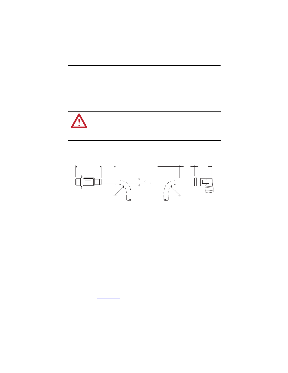
2. Before beginning any cable bend, determine the recommended bend area and the
clearance required from the features shown in the diagram.
3. Observe the following restrictions when installing these cables:
•
Network cables have a static (installation) bend radius of seven times the cable
diameter, 53.2 mm (2.09 in.).
•
When routing cables, prevent the cable from bending within 53.2 mm (2.09 in.) of
the cable connectors.
•
Bend cables only within the bend area.
•
Provide cable supports at 3 m (10 ft) intervals along the cable run to reduce tension
and flexing at the connectors and other features on the cable.
4. Apply 0.4…0.6 N•m (3.5…5.3 lb•in) of torque to fully seat the contacts and secure the
connection.
Additional specifications for each cable are available in the Kinetix Motion Accessories Technical
Data, publication
ATTENTION: Arcing or unexpected motion can occur if cables are connected or disconnected while
power is applied to the IDM system. Before working on an IDM system, disconnect power and wait
the full time interval as indicated in the warning on the IPIM module or verify the DC bus voltage at
the IPIM module measures less than 50V DC.
Failure to observe this precaution can result in personal injury or equipment damage.
47.9
(1.89)
53.2
(2.09)
7.6
(0.30)
53.2
(2.09)
14.7
(0.58)
36.8
(1.45)
Static Bend Radius
Static Bend Radius
Bend Area
2090-CNSSPRS-AA cable is shown.
Dimensions are in mm and (in.).