Lim module block diagram (2094-bl xx s) – Rockwell Automation 2094 LIM Remove/Replace Internal Components User Manual
Page 17
Publication 2094-IN009C-EN-P — April 2008
Removing and Replacing the Line Interface Module Internal Components 17
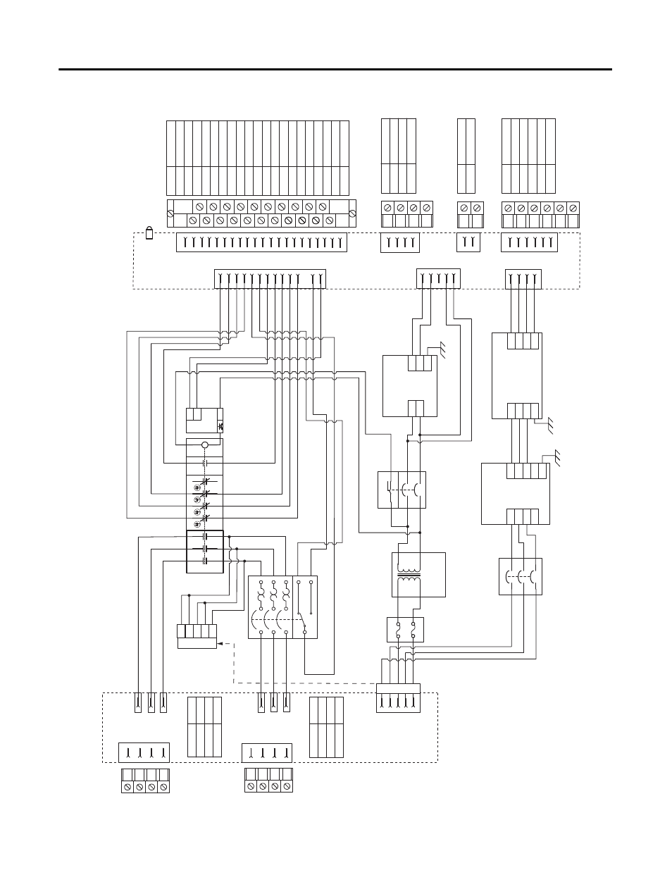
LIM Module Block Diagram (2094-BLxxS)
CB
2
11
14
12
1
3
2
4
1
3
2
4
CB
3
FB1
1
3
2
4
5
6
3
4
1
2
11
12
21
22
31
32
41
42
A1
A2
53
54
N/C
N/C
LF
2
IOL
LF
1
100-JE
E2
E1
A1
IPL
Pin 1
Pin 2
Pin 3
Pin 4
PE
L3
L2
L1
IPL
:
VAC LINE
OPL
OPL
:
VAC LOAD
Pin 1
Pin 2
Pin 3
Pin 4
PE
L3
'
L2
'
L1
'
1
2
3
4
1
2
3
4
IPL
OPL
Interface PCB
L3
L2
L1
ALRM_COM
1
3
2
4
6
AL
1c
B
M
5
CB1 (Bulletin 140U)
L3
'
L2
'
L1
'
CR1
CON
S
TA
T_12
CON
S
TA
T_22
CON
S
TA
T_32
CON
S
TA
T_54
COIL_A2
CON
S
TA
T_53
CON
S
TA
T_31
CON
S
TA
T_21
CON
S
TA
T_11
CON
S
TA
T_54
CON
S
TA
T_32
CON
S
TA
T_22
CON
S
TA
T_12
ALRM_COM
ALRM_B
COIL_E1
CON
S
TA
T_53
CON
S
TA
T_31
CON
S
TA
T_21
CON
S
TA
T_11
ALRM_M
COIL_E2
Pin 14
Pin 13
Pin 12
Pin 11
Pin 1
Pin 2
Pin 3
Pin 4
Pin 6
Pin 7
Pin 17
Pin 8
Pin 18
Pin 10
Pin 20
Pin 19
Pin 15
Pin 16
Pin 5
Pin 9
Pin 21
IO_P
W
R1
IO_COM1
IO_P
W
R1
IO_COM1
IO_P
W
R1
IO_COM1
COIL_E1
COIL_E2
ALRM_M
S
HIELD
ALRM_B
ALRM_COM
CON
S
T
A
T_11
CON
S
T
A
T_12
CON
S
T
A
T_21
CON
S
T
A
T_22
CON
S
T
A
T_31
CON
S
T
A
T_32
CON
S
T
A
T_53
CON
S
T
A
T_54
S
HIELD
IOL
:
S
TA
TU
S
I/O
1
2
3
4
5
6
7
8
9
10
11
12
13
14
15
16
17
18
19
20
21
1
2
21
20
IOL
24
V
S
tatus LED
ALRM_B
ALRM_M
ALRM_M
ALRM_COM
ALRM_B
6
5
L1
L2
PE
L1
'
L2
'
6
7
8
9
10
L3
N
1
2
3
4
L3
'
N
'
Three-phase, 1-
S
tage
Line Filter (460
VAC)
IO_P
W
R1
IO_COM1
IO_P
W
R2
IO_COM2
L1
L2
PE
24+
24+
20 A Power
S
upply
PS
1
24-
24-
COIL_A2
L1
L2
PE
L1
'
L2
'
1
2
3
4
S
ingle-phase, 1-
S
tage
Line Filter (230
VAC)
5
Pin 6
Pin 5
Pin 4
Pin 3
Pin 2
Pin 1
P2L
P2L
: AUXILIARY P
W
R OUTPUT
AUX1_L2
AUX1_L1
AUX2_L2
AUX2_L1
Pin 1
CPL
: CONTROL P
W
R OUTPUT
CPL
CTRL 2
CTRL 1
Pin 1
P1L
: BRAKE AND I/O OUTPUT
P1L
Pin 2
Pin 4
Pin 3
Pin 2
6
5
4
3
2
1
2
1
4
3
2
1
IO_P
W
R2
IO_COM2
IO_P
W
R2
IO_COM2
IO_P
W
R2
IO_COM2
4
3
2
1
2
1
6
5
4
3
2
1
CTRL1
CTRL2
Interface PCB
P2L
CPL
P1L
COIL_E2
COIL_E1
L3
TX1
460
V
::
230
V
750
VA
L3
L1
L1
L2
L2
AUX1_L2 and AUX2_L2
AUX1_L1 and AUX2_L1
1
2
3
4
1
2
3
4
J4
P4
J4_B
1
2
3
4
5
(P4)
1
1