Replace the circuit breakers – Rockwell Automation 2094 LIM Remove/Replace Internal Components User Manual
Page 10
Publication 2094-IN009C-EN-P — April 2008
10 Removing and Replacing the Line Interface Module Internal Components
3. Remove wiring from the top and bottom circuit breaker
terminals and label each wire if not already done.
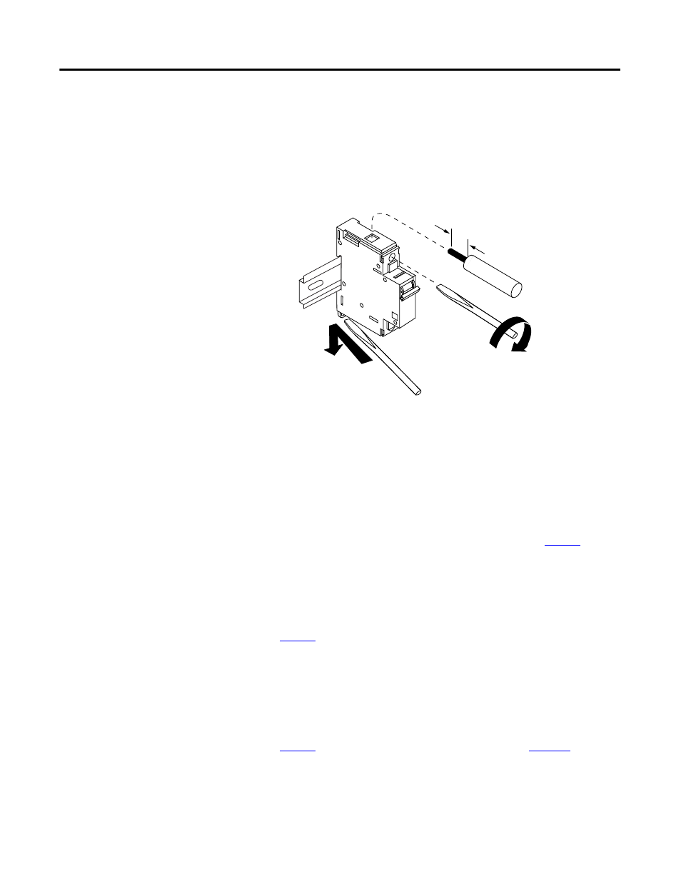
4. Using a flat-blade screwdriver, release the spring latch beneath
each circuit breaker while pulling the breaker up and away from
the DIN rail.
(1)
You may need two screwdrivers to release the control circuit breaker (CB2) and auxiliary contact latch on
2094-ALxxS, 2094-BLxxS, and 2094-XL75S modules at the same time.
Replace the Circuit
Breakers
You will need a flat-blade screwdriver to replace circuit breakers.
Follow these steps to replace LIM module circuit breakers.
1. Verify that all power is removed from the LIM module as
described in Remove/Replace the Front Cover on
2. Insert the screwdriver (as shown in the figure above) and
release the spring latch while setting the replacement breaker
into position on the DIN rail.
For replacement component part numbers, refer to the tables on
3. Remove the screwdriver to set the latch.
4. Reconnect the circuit breaker wiring. Torque set screws to
2.3…2.5 N•m (20…22 lb•in).
Refer to the wire labels (as shown in the figures beginning on
page 7
) and/or Block Diagrams (beginning on
reconnecting the circuit breaker wiring.
13.0 mm
(0.51 in.)
Removing/inserting
wires
Releasing the
spring latch
(1)
Turn screw clockwise to tighten,
counter-clockwise to loosen.