Cable installation guidelines – Rockwell Automation 2090-CPBM7DF-16RAxx SpeedTec Right-angle Standard Power and Feedback Cables User Manual
Page 4
4 SpeedTec Right-angle Standard Power and Feedback Cables
Publication 2090-IN045A-EN-P - August 2012
Cable Installation Guidelines
Follow these guidelines when installing a cable.
1. Identify the recommended installation areas and the correct offset from features before
beginning any cable bend.
Features include these areas on the cable:
•
Connectors
•
Transitions from exposed wire to insulation (for example, flying leads)
•
Exposed cable ground shields
The offset from these features should be greater than or equal to (
≥1x) the cable
diameter.
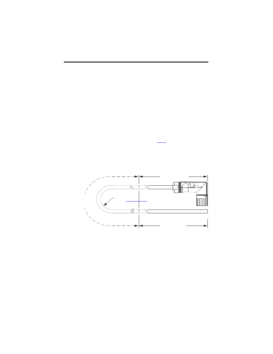
2. Keep cable bends within the bend radius specified on
3. Observe these restrictions when installing the cable:
•
The bend zone is the area in which the cable can be bent to its specified bend radius.
•
The installation areas require strain relief to minimize cable flexing, and to reduce
the possibility of cable fatigue where the cable connects to other components.
I
4. Observe these restrictions when attaching a cable connector to the motor connector:
a. Align all flat surfaces on the cable connector with the flat surface on the motor
connector.
b. Push the cable connector onto the motor connector to fully seat the connection.
c. Twist the knurled front-end of the cable connector approximately 60° to the right to
secure the connection.
TIP
You may identify each connection on a cable by attaching a label around the outer insulation of
the wire adjacent to the connection.
Bend Zone
Flex Restrictions Apply
2090-CFBM7DF-CERA
xx shown
Installation Area
300 mm (12 in.) approx.
Bend Radius
Refer to
for value.
Installation Area
300 mm (12 in.) approx.