0 mechanical/electrical description, 1 mechanical description, 2 electrical description – Rockwell Automation 57C403 115VAC High Power Output Module User Manual
Page 9
2Ć1
2.0 MECHANICAL/ELECTRICAL
DESCRIPTION
The following is a description of the faceplate LEDs, field termination
connectors, and electrical characteristics of the field connections.
2.1
Mechanical Description
The output module is a printed circuit board assembly that plugs into
the backplane of the DCS 5000/AutoMax rack. It consists of a printed
circuit board, a faceplate, and a protective enclosure. The faceplate
contains tabs at the top and bottom to simplify removing the module
from the rack. Module dimensions are listed in Appendix A.
The faceplate of the module contains a female connector socket and
16 LED indicators that show the status of the outputs. Output
signals leave the module via a multiĆconductor cable (M/N 57C370).
One end of this cable attaches to the faceplate connector, while the
other end of the cable has stakeĆon connectors that attach to a
terminal strip for easy field wiring. The faceplate connector socket
and cable plug are keyed to prevent the cable from being plugged
into the wrong module.
On the back of the module are two edge connectors that attach to
the system backplane.
2.2
Electrical Description
The output module contains 16 output circuits for 115 volt control
signals. Each group of four circuits shares a single isolated
common. Output signals have 2500 volt isolation to logic common.
Refer to the block diagram in Appendix B.
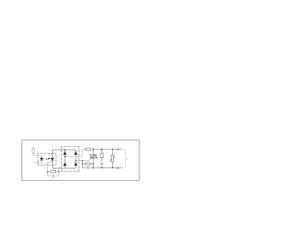
Each output circuit consists of a Triac with RC and MOV transient
supression. The Triac gate driver is optically isolated from the output
buffer. A circuit diagram is shown in figure 2.1.
ISOLATOR
RECTIFIER
FROM
OUTPUT
BUFFER
+12V
OUTPUT
130V
47W
.068 mF
Figure 2.1 Ć Typical Output Circuit
There are 16 LEDs on the faceplate of the module. The LEDs are
arranged in the same order as the output terminals on the faceplate.
They are numbered sequentially from zero through fifteen,
corresponding to the bits in the register. The LED indicators display