Rockwell Automation 1771-OAD AC(12-120V)Output Installation Instructions User Manual
Page 5
AC (12-120V) Output Module
5
Publication 1771ĆIN024B-EN-P - November 2002
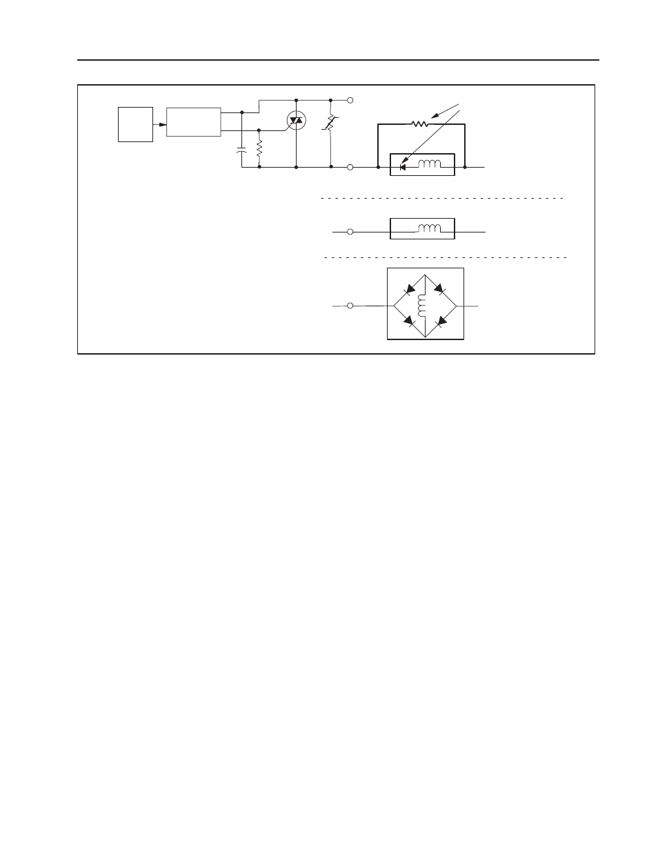
L1
Load
L2
39KΩ
Shunt Resistor required
Control
ZeroĆCrossing
OptoĆisolation
Load
L2
Shunt Resistor NOT required
L2
Shunt Resistor NOT required
SimplifiedCircuit Diagram
1. When L2 is positive with respect to
L1, capacitor C1 is charged.
2. When the polarity switches, the diode
prevents C1 from discharging.
3. With C1 charged(possibly up to line
voltage), the zeroĆcrossing optoĆtriac sees
that voltage, andwon't turn on.
4. The shunt resistor allows a bleedĆoff of
the voltage on the capacitor, allowing the
circuit to function properly.
Single rectifying diode
in series with load.
No rectifying diode.
Full wave rectifier.
Load
Note: A resistor may be
requiredif the loadis less
than 50mA.
C1
Your module receives its power through the 1771 I/O chassis
backplane from the chassis power supply. The module requires
295mA from the output of this supply. Add this to the requirements
of all other modules in the I/O chassis to prevent overloading the
chassis backplane and/or chassis power supply.
The fuse-blown jumper has two modes:
•
the preset, standard (STD) mode – displays the fuse status on
the red fuse-blown status indicator
•
the customer side indication (CSI) mode – displays the fuse
status in the input image table and on the red fuse-blown status
indicator.
This mode configures the module as a 16 point output module
that uses both the output and input image data tables of your
controller. When a fuse blows, all 16 bits in the associated input
image table will turn on (1).
For example, if you install the module in a PLC-5 system and
address the module as O:012, then the fuse status bits are in
I:012.
To monitor the status of the module fuse, make certain that your user
program monitors the module’s input image table for ‘‘on” bits.
Calculate Power
Requirements
Select the Mode of the
Fuse-Blown Jumper