Interpreting the status indicators troubleshooting – Rockwell Automation 1771-OAD AC(12-120V)Output Installation Instructions User Manual
Page 11
AC (12-120V) Output Module
11
Publication 1771ĆIN024B-EN-P - November 2002
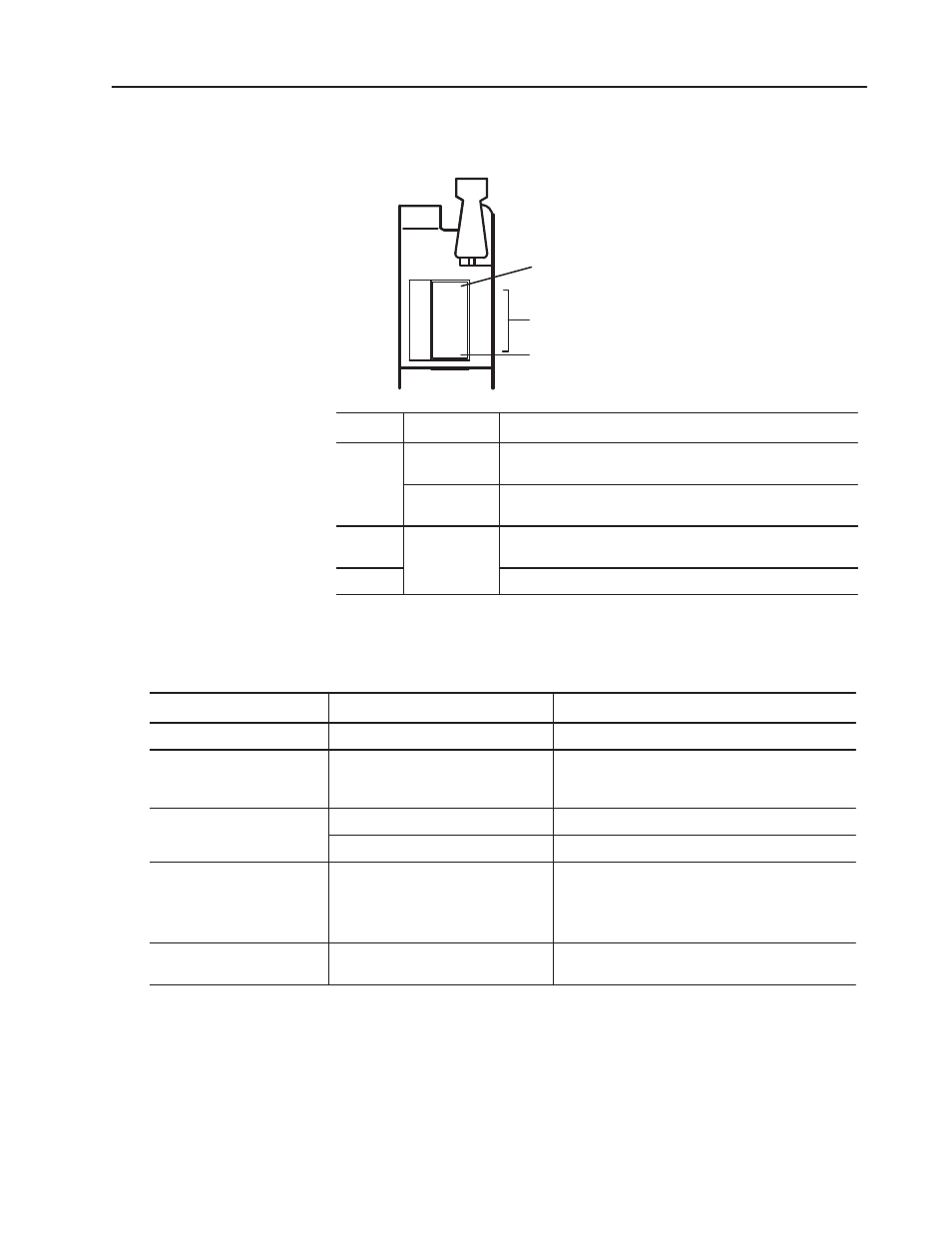
The front panel has one green module active indicator, 16 red status
indicators, and one red fuse-blown indicator.
ACTIVE
00
01
02
03
04
05
06
07
10
11
12
13
14
15
16
17
Module Active
Indicator (green)
00 to 17 Status
Indicators (red)
FUSE
Fuse Blown
Indicator (red)
12225-I
Indicator
Mode
Description
Active
Standard Mode
(STD)
The active indicator lights when the rack power supply has properly
established5V dc andthe processor is in RUN mode.
Customer Side
Indication (CSI)
The active indicator lights when the rack power supply has properly
established5V dc.
Status
STD or CSI
The status indicators light when voltage is present at the respective
output terminal.
Fuse
The fuse indicator lights when the fuse has blown or been cleared.
Use this table to help you interpret the 1771-OAD status indicators
and to troubleshoot module and system faults.
Indicator Status
Description of Fault or System Status
Action to Take
Module active ON (green)
Normal Indication.
None.
Module active ON (green) and
Output status ON (red)
Check voltage at output point on the
swing arm.
If voltage is present, take no action. If no voltage is
present, check the fuse. If the fuse is OK, replace the
module.
Module active ON (green) and
Output status OFF
No voltage.
None.
Output status OFF
Voltage on the terminal.
Replace the module.
Module active OFF and
Output status ON (red) or OFF
1. The processor is in program mode.
2. Module not functioning properly.
1. If module is in normal mode, take no action. If module
is in CSI mode replace module.
2. Check the chassis power supply andprocessor. If they
are OK, replace the module.
Fuse blown (red)
Outputs will not turn on.
Replace the fuse. If fuse replacement does not correct
the problem, replace the module.
Interpreting the Status
Indicators
Troubleshooting