I/o module groups – Rockwell Automation 1771-IAN 120V Input Module Installation Instructions User Manual
Page 8
AC (120V) Input Module
8
Publication 1771-IN032B-EN-P - July 2002
I/O Module Groups
Each module condenses 2 full module groups (32 inputs) into each
I/O chassis slot. For example:
–
Module group 1 = inputs 00 through 17
–
Module group 2 = inputs 00 through 17 (module group 2
represents the second set of inputs).
Terminals 1 through 20 represent module group 1, with terminals 9,
10, 19 and 20 ac low (L2). Terminals 21 through 40 represent
module group 2, with terminals 29, 30, 39 and 40 ac low (L2).
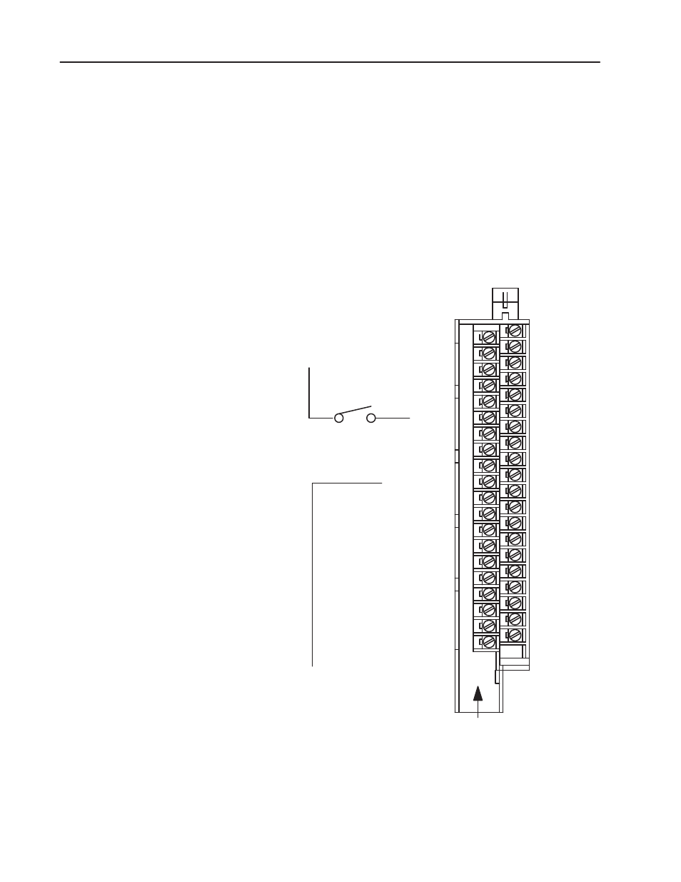
Connection Diagram for the 1771–IAN ac Input Module
Note: Terminals on the left are
even numbered(2 thru 40) , andterminals on the right
are oddnumbered(1 thru 39).
Input 01
Input 03
Input 05
Input 07
Input 11
Input 13
Input 15
Input 17
Input 00
Input 02
Input 04
Input 06
Input 10
Input 12
Input 14
Input 16
Input 03
Input 05
Input 07
Input 11
Input 13
Input 15
Input 17
Input 02
Input 04
Input 06
Input 10
Input 12
Input 14
Input 16
2
4
6
8
10
12
14
16
18
20
22
24
26
28
30
32
34
36
38
40
Input 00
Common 0 (L2)
Common 1 (L2)
Common 2 (L2)
common 3 (L2)
Common 0 (L2)
Common 1 (L2)
Common 2 (L2)
Common 3 (L2)
Input 01
(Actual wiring runs in this direction.)
ac Low
ac High
11854-I
Terminals 1 through 20 represent module group
1,with terminals 9, 10, 19 and20 ac low (L2).
Terminals 21 through 40 represent module group
2, with terminals 29, 30, 39 and40 ac low (L2).
Module group 1 = inputs 00 through 17
Module group 2 = inputs 00 through 17 (module
group 2 represents the secondset of inputs.)
If multiple power supplies are used, do not exceed the specified isolation voltage.