Rockwell Automation 1771-OAN Installation Instructions User Manual
Page 5
AC (120/240V) Output Module
5
Publication 1771ĆIN031B-EN-P - November 2002
!
ATTENTION
Preventing Electrostatic Discharge
This equipment is sensitive to electrostatic
discharge, which can cause internal damage and
affect normal operation. Follow these guidelines
when you handle this equipment:
•
Touch a grounded object to discharge
potential static.
•
Wear an approved grounding wriststrap.
•
Do not touch connectors or pins on
component boards.
•
Do not touch circuit components inside the
equipment.
•
If available, use a static–safe workstation.
•
When not in use, keep modules in appropriate
static–safe packaging.
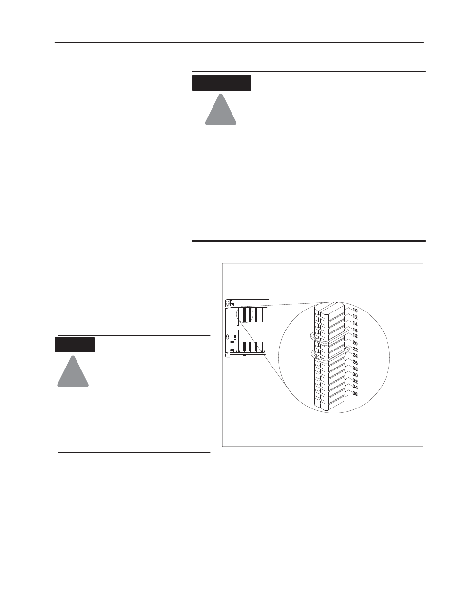
Key the Backplane
Connector
Place your module in any slot in the chassis
except the leftmost slot which is reserved for
processors or adapters.
Observe the following
precautions when inserting or
removing keys:
•
insert or remove keys with
your fingers
•
make sure that key placement
is correct
Incorrect keying or the use of a
tool can result in damage to the
backplane connector and possible
system faults.
!
ATTENTION
Position the keying bands in the backplane connectors to correspond to
the key slots on the module.
Place the keying bands:
between 16 and 18
between 22 and 24
You can change the position of these bands if
subsequent system design and rewiring makes
insertion of a different type of module necessary.
Upper
Connector
11022ĆI
I/O chassis
Initial Handling
Procedures