Configure the module – Rockwell Automation 1771-IFE/C INSTL.INSTRUCTIONS ANALOG INPU User Manual
Page 10
Analog Input Module
10
Publication 1771Ć5.45 - July 1997
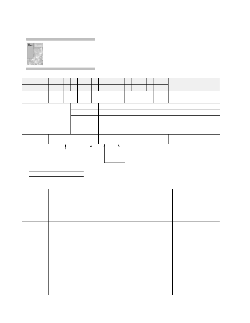
Because of the many analog devices available and the wide variety
of possible applications, you must configure the module to conform
to the analog device and specific application that you have chosen.
Use the configuration information below to configure your module
to your specifications.
Dec. Bits
15 14 13 12 11 10 09
08
07 06 05 04 03 02 01 00
Description
Octal Bits
17 16 15 14 13 12 11
10
07 06 05 04 03 02 01 00
Description
Word 1
8
7
6
5
4
3
2
1
Range Selection Ć Channels 1 - 8
2
16
15
14
13
12
11
10
9
Range Selection Ć Channels 9 - 16
Input range selections allow the
Bit 01
Bit 00
Voltage or Current Input
Input range selections allow the
user to configure the inputs for any of
7 i
t lt
t
T
0
0
1 to 5V dc, 4 to 20mA (default)
user to configure the inputs for any of
7 input voltage or current ranges. Two
bits are required for each channel.
0
1
0 to 5V dc, 0 to 20mA
bits are required for each channel.
Bits 00 and 01 for channel 1, bits 02
and 03 for channel 2, etc.
1
0
Ć5 to +5V dc, Ć20 to +20mA
and 03 for channel 2, etc.
1
1
Ć10 to +10V dc, 0 to 10V dc
3
Real Time Sampling
Data
Format
Input
Type
Digital Filter
Real time sampling, data format, input
type and digital filter
Digital filter reduces effect of noise on input. (Default is no
filter.)
Input type, set bit for differential mode on all channels.
Reset (0) = singleĆended inputs (default)
Set (1)
= differential inputs
Real time sampling - Default is no RTS.
Data format - set to match
your processor.
BCD (default)
Reserved
Two's complement binary
Signed magnitude binary
Bit 10
(12)
Bit 09
(11)
0 0
0 1
1 0
1 1
4
Minimum sign bits, when set, designate negative minimum scaling values for the
corresponding input channels. Bit 00 corresponds to channel 1, bit 01 corresponds to
channel 2, etc.
Sign Bits, minimum scaling values
5
Maximum sign bits, when set, designate maximum scaling values that are negative.
Maximum scaling value must be greater than minimum on any particular channel. Bit 00
corresponds to channel 1, bit 01 corresponds to channel 2, etc.
Sign Bits, maximum scaling values
6, 8, 10, 12, 14, 16,
18, 20, 22, 24, 26,
28, 30, 32, 34, 36
Minimum scaling values for each channel. Enter in BCD format.
Channel 1 Ć minimum scaling
7, 9, 11, 13, 15, 17,
19, 21, 23, 25, 27,
29, 31, 33, 35, 37
Maximum scaling values for each channel. Enter in BCD format.
Channel 1 Ć maximum scaling
38
Offset calibration - Each bit represents a channel (bit 00 to channel 1, bit 01 to channel
2, etc.). When the bit is set, and a BTW has been sent, the module will read the channels
and adjust the offset to analog ground potential. In differential mode, bits 08 thru 15 (10
thru 17 in octal) are ignored. In current mode, apply 0mA.
Offset Calibration
39
Gain calibration - Each bit represents a channel (bit 00 to channel 1, bit 01 to channel 2,
etc). When the bit is set, and a BTW has been sent, the module will read the channels and
adjust the gain correction values. If used on +, 0 to 5, or 1 to 5V ranges, a value of 5V is
expected. If used on +10V range, 10V is expected. In differential mode, bits 08 thru 15 (10
thru 17 in octal) are ignored. In current mode, apply 20mA.
Gain Calibration
For detailed configuration
information, see chapter 2 of
your Analog Input User Manual
(publication 1771Ć6.5.115).
Configure the Module