Rockwell Automation 1771-A2BSS_A3B1SS Install Instruc Universal I/O Chassis User Manual
Page 11
Universal I/O Chassis
11
Publication 1771–5.60 – May 1999
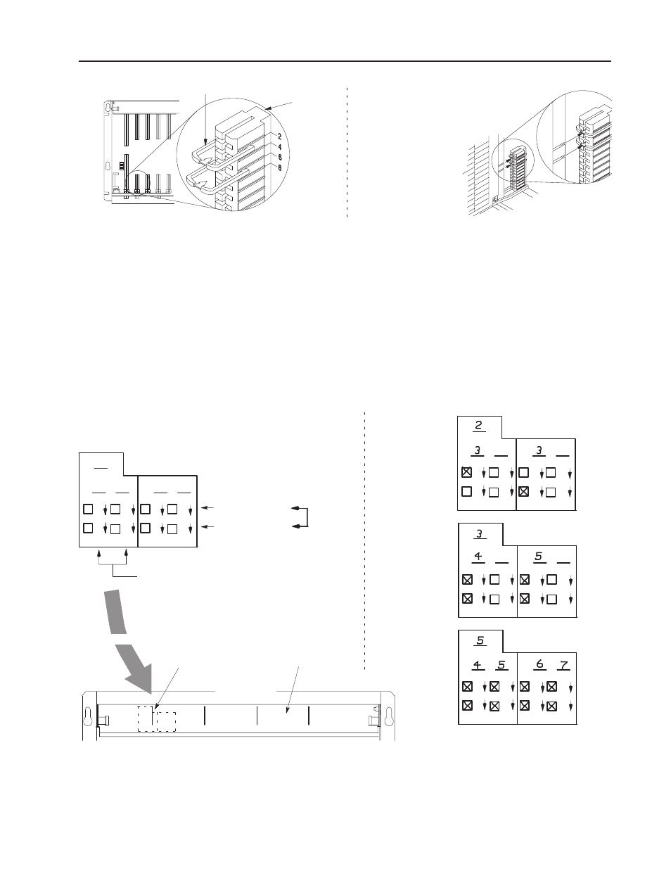
backplane
connector
Each I/O module is slotted in two places
at the rear edge of the circuit board.
These slots are intended to mate with the
plastic keys supplied with each chassis.
keying bands
I/O chassis
I/O module
I/O chassis
backplane connector
Repeat for each module you install.
b.
install the module.
Important:
Firmly press the module into the chassis backplane
connector. The chassis locking bar will not close if
any modules are not seated properly.
3. Swing the chassis locking bar down into place to secure the
modules. Make sure the locking pins engage.
4. Apply the I/O group labels over the scored lines on the I/O
chassis locking bar as shown below. On each label, record the
I/O rack number, I/O group number and terminal numbering for
each module.
R
G
G
00
07
10
17
00
07
10
17
00
07
10
17
00
07
10
17
G
G
R
G
G
00
07
10
17
00
07
10
17
00
07
10
17
00
07
10
17
G
G
R
G
G
00
07
10
17
00
07
10
17
00
07
10
17
00
07
10
17
G
G
Examples:
2–slot addressing
(8-point I/O
modules)
1–slot addressing
(16-point I/O
modules)
1/2–slot addressing
(32-point I/O
modules)
R
G
G
00
07
10
17
00
07
10
17
00
07
10
17
00
07
10
17
G
G
A digital 32-point I/O module
in any slot has its terminals
numbered for two I/O groups.
A digital 8-point
I/O module has its
terminals numbered:
A digital 16-point
I/O module has its
terminals numbered:
00–07 (left slot)
or
10–17 (right slot)
00–07
10–17
and
1st I/O group – 00–07 and 10–17
2nd I/O group – 00–07 and 10–17
12448-I
locking bar
scored line
front of chassis
placement
I/O Group Label
5. Use your module’s installation data to make other wiring
connections.