Install your i/o modules – Rockwell Automation 1771-A2BSS_A3B1SS Install Instruc Universal I/O Chassis User Manual
Page 10
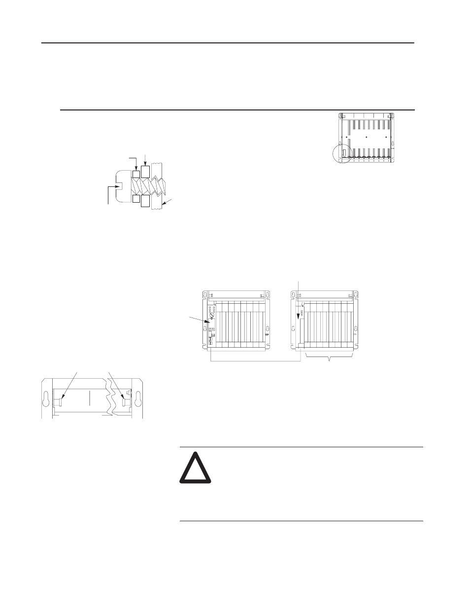
front of chassis
locking-bar pins
12453-I
Universal I/O Chassis
10
Publication 1771–5.60 – May 1999
Important:
Use the installation data for your power supply or
power supply chassis to properly mount it to your I/O
chassis.
This I/O chassis
Has power connectors located
С
С
УУ
УУ
ФФ
ФФ
ФФ
С
С
УУ
УУ
power supply mounting bracket
flat washer
mounting screw
I/O Chassis
ФФ
ФФ
12447-I
If you mount a power supply to any I/O chassis, place the flat washers
provided between each mounting screw and the power supply mounting
bracket. If you do not use the flat washers, the mounting screw intrudes
into the I/O chassis and interferes with module insertion.
1771-A2BSS
1771-A3B1SS
The left-most slot of each chassis accepts either a processor module
or an I/O adapter module. The other slots in the chassis accept
communication modules, I/0 modules and power-supply modules.
communication cable
I/O modules
I/O adapter module
11865
1771-A2BSS I/O chassis
1771–A2BSS I/O chassis
PLC-5
Processor
To insert a module:
1. Pull the locking-bar pins to release the locking bar and swing up.
2. Use the installation data/user manual for your module to:
a.
position the keying bands in the backplane connectors to
correspond to the key slots on the module. This prevents
you from inserting the wrong module in this slot.
!
ATTENTION: Observe the following precautions when
inserting or removing keys:
•
insert or remove keys with your fingers
•
make sure that key placement is correct
Incorrect keying or the use of a tool can result in damage
to the backplane connector and possible system faults.
Install Your I/O Modules