Mounting the controller, General considerations – Rockwell Automation 1763-L16xxx MicroLogix 1100 Programmable Controllers Installation Instructions User Manual
Page 9
9
Publication 1763-IN001B-EN-P - September 2007
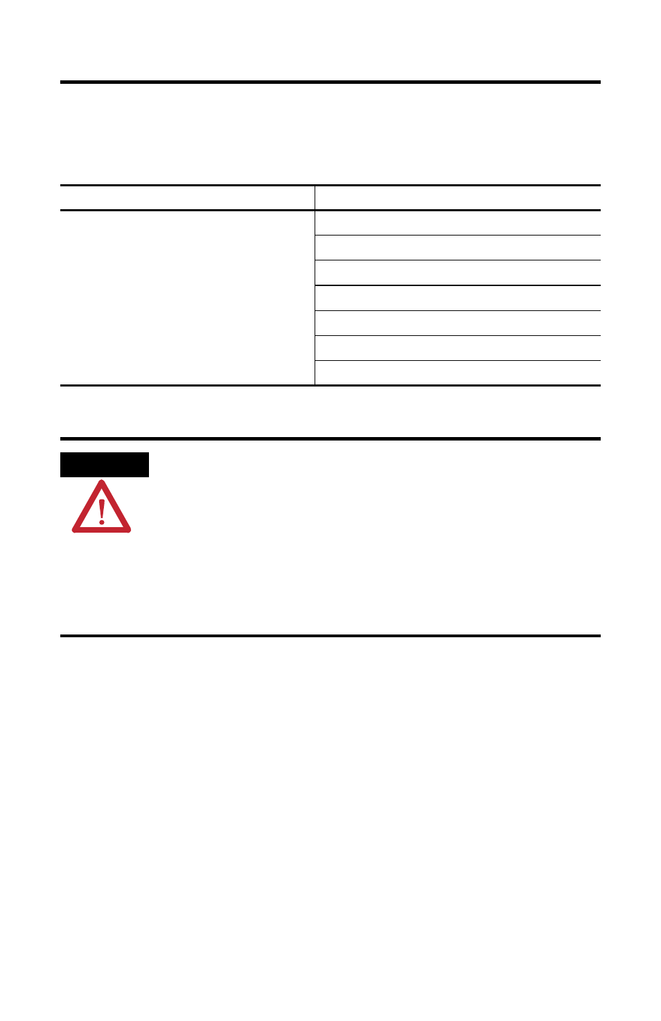
Use only the following communication cables in Class I, Division 2 hazardous
locations.
Mounting the Controller
General Considerations
Most applications require installation in an industrial enclosure to reduce the effects
of electrical interference and environmental exposure. Locate your controller as far
as possible from power lines, load lines, and other sources of electrical noise such
as hard-contact switches, relays, and ac motor drives. For more information on
proper grounding guidelines, see the Industrial Automation Wiring and Grounding
Guidelines, publication 1770-4.1.
Environment Classification
Communication Cables
Class I, Division 2 Hazardous Environment
1761-CBL-AC00 Series C or later
1761-CBL-AM00 Series C or later
1761-CBL-AP00 Series C or later
1761-CBL-PM02 Series C or later
1761-CBL-HM02 Series C or later
2707-NC9 Series C or later
1763-NC01 Series A or later
ATTENTION
UNSUPPORTED CONNECTION
Do not connect a MicroLogix 1100 controller to another MicroLogix family controller
such as MicroLogix 1000, MicroLogix 1200, or MicroLogix 1500 using a 1761-CBL-AM00
(8-pin mini-DIN to 8-pin mini-DIN) cable or equivalent.
This type of connection will cause damage to the RS-232/485 communication port
(Channel 0) of the MicroLogix 1100 and/or the controller itself. Communication pins
used for RS-485 communications are alternately used for 24V power on the other
MicroLogix controllers.