Wiring options for the i/o module – Rockwell Automation 1762-OB32T MicroLogix Solid State 24V DC Source Output User Manual
Page 13
MicroLogix 1762-OB32T Solid State 24V DC Source Output Module 13
Publication 1762-IN020B-EN-P - June 2013
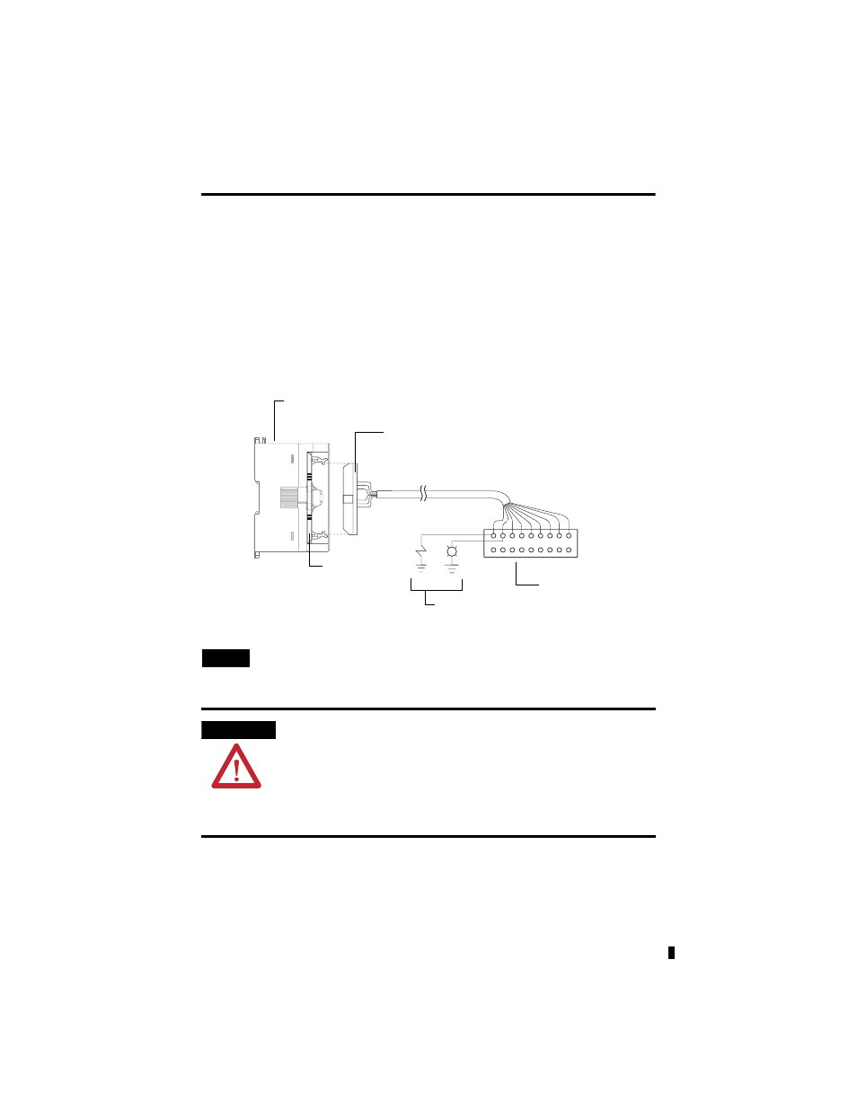
Wiring Options for the I/O Module
Included with your 32-point output module is a keyed 40-pin female connector and crimp type
pins. These components allow you to wire I/O devices to the module using a 40-conductor cable
or individual wires. Refer to Assemble the Wire Contacts on page 15 for more information on
connector/pin assembly instructions.
When assembled, align the female connector over the module’s male header using the keying slot
as a guide. Firmly lock them together with the upper and lower retaining arms.
Wire the 1746-N3 Connector
TIP
If you decide to build your cable using another 1746-N3 to terminate the cable at the
1492 Interface Module end, wire it in the following manner: Pin 1 to Pin 1, Pin 2 to
Pin 2, Pin 3 to Pin 3, etc.
ATTENTION
Maximum user cable length is dependent on how much voltage drop
(current x (ohms/ft.) x (feet)) the user’s system can tolerate. The user’s system
should take into account the minimum turn-on voltage required by external loads
connected to the 32-point output module, the minimum turn-on voltage required
by the 32-point input module and all of the voltage drops associated with wiring
to and from the load, sensors, terminal connectors, power sources and the
module itself.
Keyed female
connector (1746-N3)
Included with 32-point
output modules.
44924
32-point output module
Keyed male
MIL-C-083503
connector
Panel lights, buttons,
sensors.
Contact pins provided with
female connector can
accept 22...26 AWG wires.
User terminal connector