Mounting the terminal base unit on a din rail – Rockwell Automation 1794-TB62DS, 1794-TB37DS, 1794-TB62EXD4X15, 1794-TB37EXD4CM8, 1794-TB37EXD4VM8 FLEX I/O D-Shell Terminal Base Units User Manual
Page 2
2 FLEX I/O D-Shell Terminal Base Units and Distribution Boards
Publication 1794-IN107A-EN-P - March 2005
FLEX I/O D-Shell Terminal Base Units
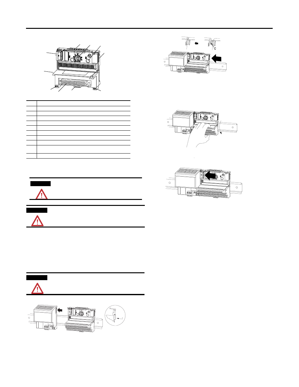
Mounting the Terminal Base Unit on a DIN Rail
1. Remove the cover plug (if used) in the male connector of the unit to which you
are connecting this terminal base unit.
2. Check to make sure the 16 pins in the male connector on the adjacent device are
straight and in line so that the mating female connector on this terminal base
unit will mate correctly.
3. Make certain the female connector (C) is fully retracted.
4. Position the terminal base unit on the 35 x 7.5 DIN rail (A) (A-B pt no.
199-DR1).
5. Rotate the terminal base onto the DIN rail with the top of the rail hooked under
the lip on the rear of the terminal base. Use caution to make sure that the
female flexbus connector does not strike any of the pins in the mating
connector.
6. For specific wiring information, refer to the installation instructions for the
module you are installing in this terminal base.
7. Repeat the above steps to install the next terminal base.
Description
1
Terminal base unit
2
Female flexbus connector
3
Module locking latch
4
Keyswitch - set to the position required for the installed module
5
Mounting holes for panel mounting
6
Male flexbus connector
7
Cover plug for male flexbus connector
8
Locking tab
9
D-shell connector -1794-TB37DS - 37 pin D-shell connector;
1794-TB62DS - 62 pin D-shell connector
10
User power connectors
ATTENTION
During mounting of all devices, be sure that all debris (metal chips,
wire strands, etc.) is kept from falling into the module. Debris that
falls into the module could cause damage on power up.
ATTENTION
Do not remove or replace a terminal base unit when power is applied.
Interruption of the flexbus can result in unintended operation or
machine motion.
ATTENTION
Do not force the terminal base into the adjacent base/adapter.
Forcing the units together can bend or break the hook and allow the
units to separate and break communication over the backplane.
3
2
6, 7
8
9
4
1
5
10
10
Position the terminal base at a slight angle and hooked over the
top of the DIN rail.
A
B
A
C
DIN rail
Slide the terminal base over tight against the adapter.
Make sure the hook (C) on the terminal base slides under
the edge of the adapter and the flexbus connector is fully retracted.
Press down on the terminal base to lock it on the DIN rail.
If the terminal base does not lock into place, use a screwdriver or
similar device to open the locking tab, press down on the base, and
release the locking lever to lock the base in place.
Gently push the flexbus connector into the side of the adapter
to complete the backplane connection.