Wiring options for the i/o module – Rockwell Automation 1769-OV32T Compact Module User Manual
Page 10
10 Compact 32-point Solid-state 24V dc Sink Output Module
Publication 1769-IN073B-EN-P - September 2005
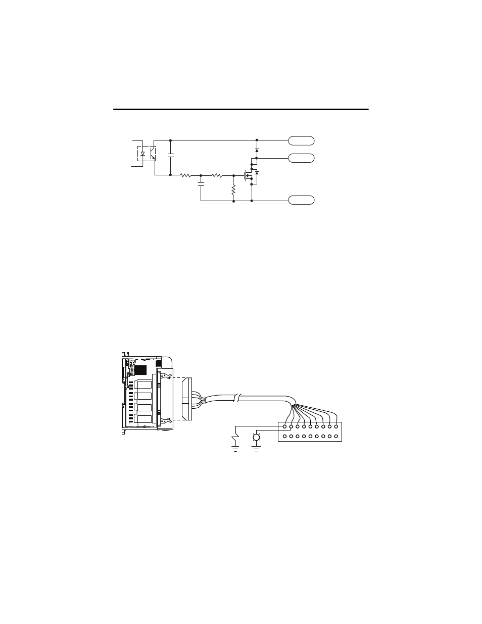
Simplified Output Circuit Diagram
Wiring Options for the I/O Module
Included with your 32-point I/O module is a keyed 40-pin female connector and crimp type
pins. These components allow you to wire I/O devices to the module using a 40-conductor
cable or individual wires. Refer to page 12 for connector/pin assembly instructions. When
assembled, align the female connector over the modules male header using the keying slot as
a guide. Firmly lock them together with the upper and lower retaining arms. 1492 pre-wired
cables and interface modules can be used for connecting external I/O.
There are two options for wiring the 32-point I/O module.
Option 1 - Wiring the 1746-N3 Connector
(1)
Maximum user cable length is dependent on how much voltage drop (current x (ohms/ft.) x (feet)) the user’s system can
tolerate. The user’s system should take into account the minimum turn-on voltage required by external loads connected to
the 32-point output module, the minimum turn-on voltage required by the 32-point input module, and all of the voltage
drops associated with wiring to and from the load, sensors, terminal blocks, power sources and the module itself.
31560A-M
~
+VDC
OUT
DC COM
31561-M
Keyed Female Connector (1746-N3)
Included with 32-Point I/O Modules
Contact pins provided with female
connector can accept 22 to 26 AWG
wires.
(1)
User Terminal Block (For
wire termination, refer to
page 14 for the wiring
diagrams of the I/O modules.)
Panel Lights,
Buttons, Sensor,
etc.
Keyed Male
MIL-C-83503
Header
32 Point
I/O Module