Controlnet network status leds, Fieldbus network status leds – Rockwell Automation 1788-CN2FF ControlNet-to-FOUNDATION Fieldbus H1 Linking Device User Manual User Manual
Page 17
1788-6.5.1 - January 1999
Hardware Installation and Configuration
2-7
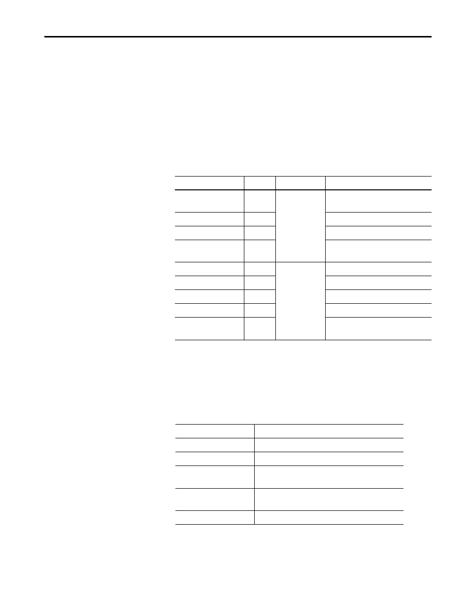
ControlNet Network Status LEDs
The ControlNet network status LEDs are located on the front of the linking
device, beside the ControlNet BNC connectors, as shown in Figure 1.2.
They indicate the state of the ControlNet connected to the BNC connectors.
These LEDs do not reflect anything about the status of the network if the
linking device is connected to the network through the network access port
(NAP). If more than one state is present, the LEDs always reflect the
highest priority status present on the network. Table 2.B describes the LED
states and the priority of each status.
Fieldbus Network Status LEDs
Each Fieldbus port on the linking device has an LED to indicate the
functional states of the port. Table 2.C describes each state.
Table 2.B Description of ControlNet Network Status LED States
LED State
Priority
How to View
Cause
Both steady off
1
(highest)
View together
Reset or no power
Both steady red
2
Failed to link interface to ControlNet
Alternating red & green
3
Self testing
Alternating red
4
Bad node configuration (such as
duplicate ControlNet network address)
Steady off
5
View
independently
Channel disabled or not supported
Flashing red & green
6
Invalid link configuration
Flashing red
7
Link fault or no frames received
Flashing green
8
Temporary channel error or listen only
Steady green
9
(lowest)
Normal operation
Table 2.C Description of Fieldbus Network Status LED States
LED State
Meaning
Off
Fieldbus port not receiving packets
Steady green
Fieldbus port is alive as Link Active Scheduler
Flashing red and green
Fieldbus port is seeing traffic, but is at a default or
visitor address
Flashing red
Fieldbus port encountered transient, non-fatal network
error
Steady red
Fieldbus port encountered fatal network error