Troubleshoot with the indicators, Maximum output data format (base modules -4b4p) – Rockwell Automation 1791R-XXXX CompactBlock Distributed I/O on Remote I/O Series D I.I. User Manual
Page 31
CompactBlock Distributed I/O on Remote I/O Series D 31
Publication
1791R-IN002B-EN-P - August 2003
Troubleshoot with the Indicators
The 1791R I/O module has the following indicators:
• Status indicator - base only
• Comm indicator - base only
• I/O status indicators - base and expansion
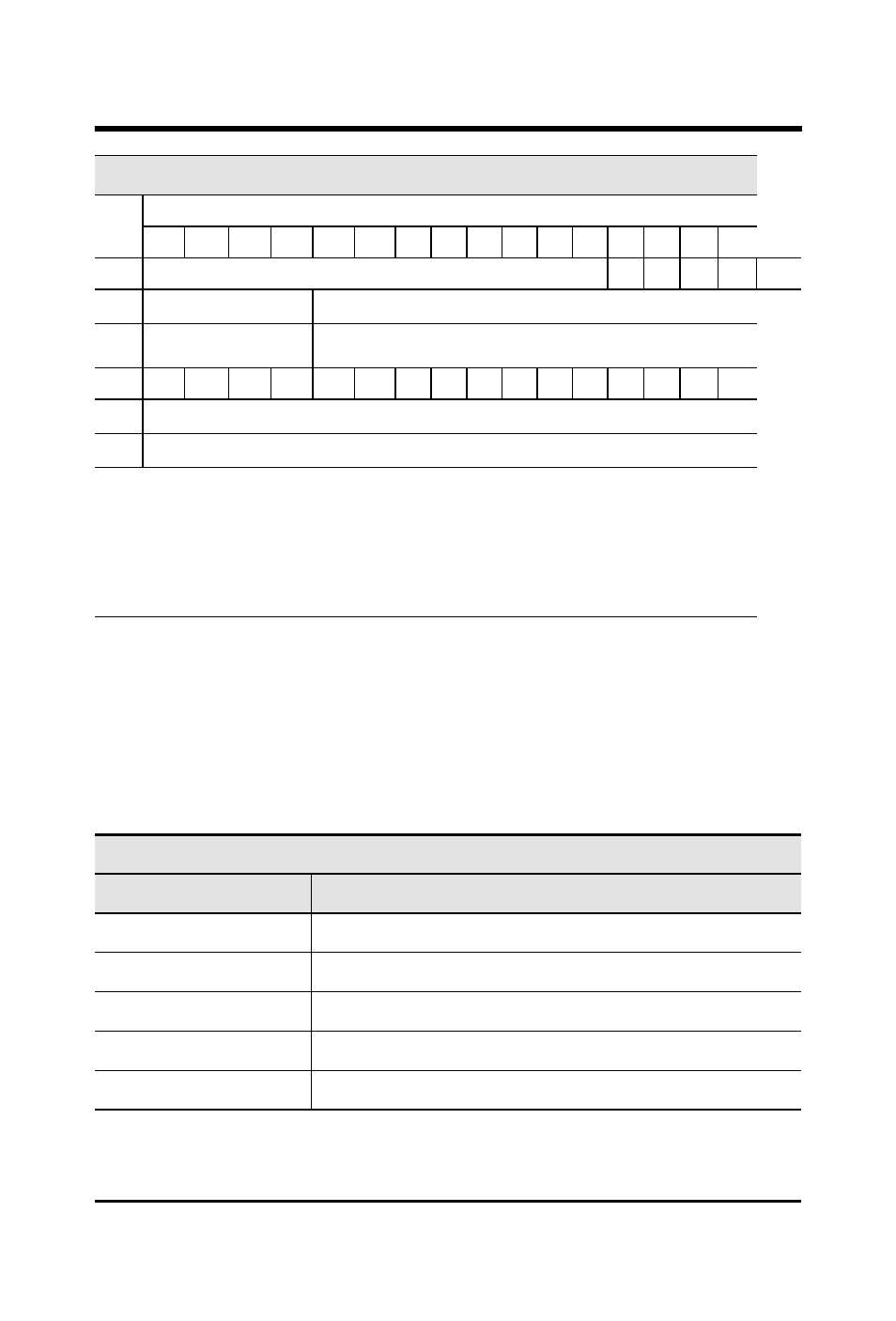
Maximum Output Data Format (Base Modules -4B4P)
Word
Bit Position
15
14
13
12
11
10
9
8
7
6
5
4
3
2
1
0
0
Reserved
O3
O2
O1
O0
Base
1
Reserved
Analog Output Data Channel 0
2
Reserved
Analog Output Data Channel 1
3
OE
HLS
R
IF
IR3
IR2
IR1
IR0
IM3 IM2 IM1 IM0 OR1 OR0 OM1 OM0
4
Reserved
5
Reserved
OM x Output Mode Selection
Set “0”: Voltage Mode
Set “1”: Current Mode
OR x Output Range Selection on Current ModeSet “0”: 4-20mA
Set “1”: 0-20mA
IM x Input Channel Mode Select
Set “0”: Voltage Mode
Set “1”: Current Mode
IR x Input Range Select on Current Mode
Set “0”: 4-20mA
Set “1”: 0-20mA
IF
Input Filter Selection
Set “0”: 50Hz
Set “1”: 60Hz
R Reserved;
HLS HLS/OFF
Set “0”: Output Reset
Set “1”: Hold Last State
OE
Output Enable
Set “0”: Output Disabled
Set “1”: Output Enabled
(Output is 0mA at 0-20mA mode and 4-20mA mode
and 0V at 0-10V mode when this bit is 0)
Status Indicator
Indication:
Status:
Off
No power
Red
Hardware or software error, power is low
Green
Normal operation
Flashing Red
Comm failure 1*
Flashing Red/Orange
Expansion error
*1 Comm fail = communication cable disconnected, 100ms between valid frames, no more than
255 valid frames between valid frames addressed to module, 20ms idle time exceeded.
**2 COMM and STATUS will alternately flash when processor restart lockout is selected, a
fault has occurred and the processor is communicating with the module.