North american hazardous location approval, Installing your thermocouple or rtd input module – Rockwell Automation 1794-IT8_IR8 FLEX I/O 8 Thermocouple Input Module User Manual
Page 2
2
Publication 1794-IN021D-EN-P - August 2003
North American Hazardous Location Approval
The following analog input modules are Hazardous Location approved:
1794-IR8 and 1794-IT8.
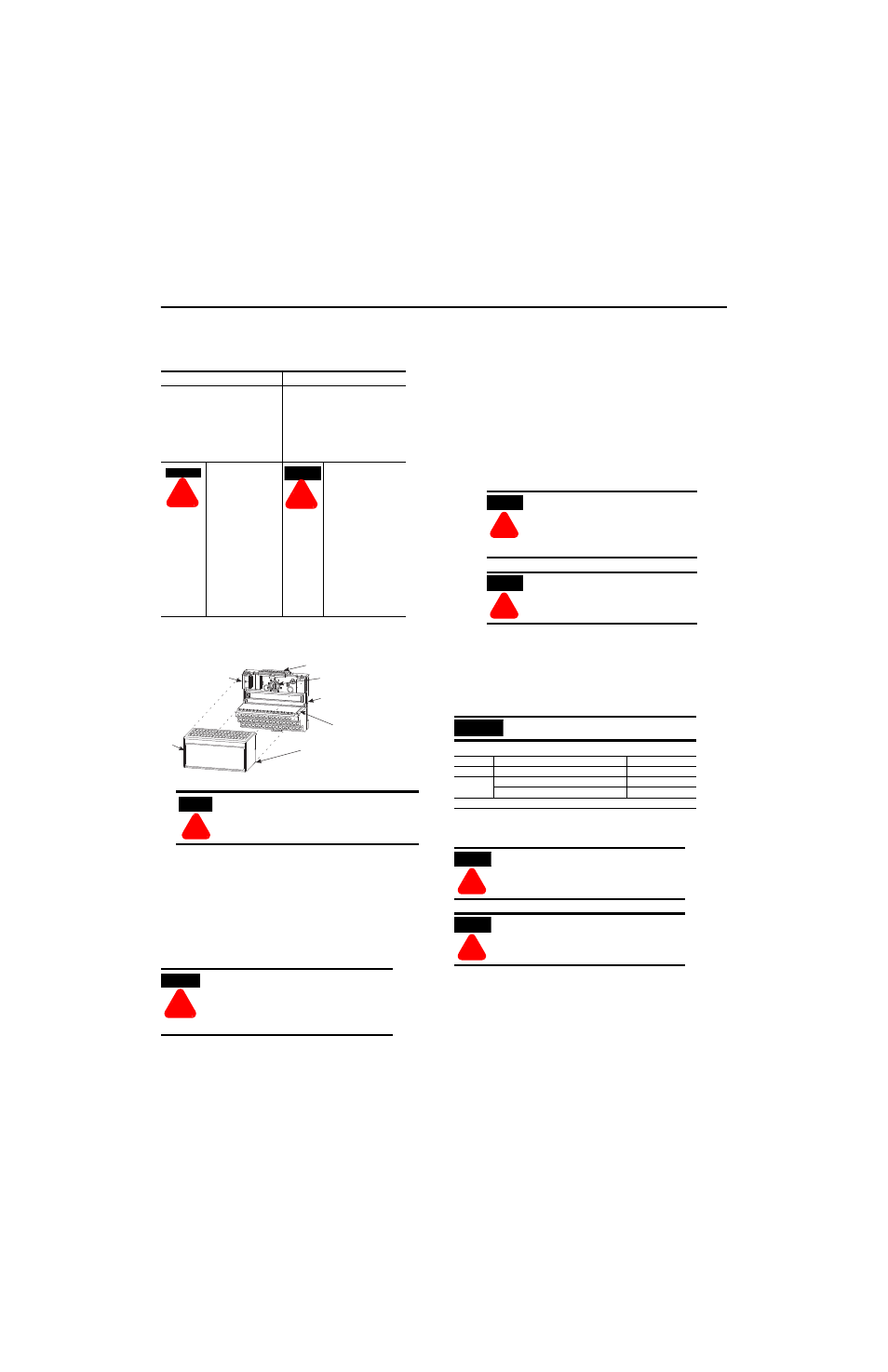
Installing Your Thermocouple or RTD Input Module
The module mounts on a 1794 terminal base.
1. Rotate the keyswitch (1) on the terminal base (2) clockwise to position
3 as required for this type of module.
2. Make certain the flexbus connector (3) is pushed all the way to the left
to connect with the neighboring terminal base/adapter. You cannot
install the module unless the connector is fully extended.
3. Make sure the pins on the bottom of the module are straight so they
will align properly with the connector in the terminal base.
4. Position the module (4) with its alignment bar (5) aligned with the
groove (6) on the terminal base.
5. Press firmly and evenly to seat the module in the terminal base unit.
The module is seated when the latching mechanism (7) is locked into
the module.
Connecting Wiring for 1794-TB2, -TB3, -TB3S, -TB3T and -TB3TS
Terminal Base Units
1. Connect individual high and low signal wiring to numbered terminals
on the 0-15 row (A) as indicated in the table. Use Belden 8761 cable
for mV signal wiring, or the appropriate thermocouple wire for your
thermocouples. (For more accurate readings in mV mode, use the
1794-TB3T or -TB3TS terminal base unit.)
2. Connect individual channel signal returns to the associated terminal
on row (B) as shown in the wiring table.
3. Connect individual channel shield returns to the associated terminal
on row (B) for 1794-TB3 or -TB3S or row (C) for the 1794-TB3T or
-TB3TS as shown in the wiring table..
4. Connect +24V dc power to terminal 34 on the 34-51 row (C).
5. Connect 24V dc common to terminal 16 on the 16-33 row (B).
6. 1794-IT8 only: On 1794-TB3T or -TB3TS terminal base units,
connect cold junction compensation (CJC) wiring to terminals 36, 37
and 38 for inputs 0-3, and terminals 47, 48 and 49 for inputs 4-7.
Connect the tail of the CJC to any of the associated thermocouple
input terminals: 0 thru 7 for CJC connected to terminals 36, 37 and
38; or 8 thru 15 for CJC connected to terminals 47, 48 and 49.
The tail of the CJC shares a terminal with an input.
The following information applies when
operating this equipment in hazardous locations:
Informations sur l’utilisation de cet équipement en
environnements dangereux :
Products marked “CL I, DIV 2, GP A, B, C, D” are suitable
for use in Class I Division 2 Groups A, B, C, D,
Hazardous Locations and nonhazardous locations only.
Each product is supplied with markings on the rating
nameplate indicating the hazardous location
temperature code. When combining products within a
system, the most adverse temperature code (lowest “T”
number) may be used to help determine the overall
temperature code of the system. Combinations of
equipment in your system are subject to investigation
by the local Authority Having Jurisdiction at the time of
installation.
Les produits marqués "CL I, DIV 2, GP A, B, C, D" ne
conviennent qu’à une utilisation en environnements de
Classe I Division 2 Groupes A, B, C, D dangereux et non
dangereux. Chaque produit est livré avec des marquages
sur sa plaque d’identification qui indiquent le code de
température pour les environnements dangereux.
Lorsque plusieurs produits sont combinés dans un
système, le code de température le plus défavorable
(code de température le plus faible) peut être utilisé
pour déterminer le code de température global du
système. Les combinaisons d’équipements dans le
système sont sujettes à inspection par les autorités
locales qualifiées au moment de l’installation.
EXPLOSION HAZARD
•
Do not disconnect equipment
unless power has been
removed or the area is known
to be nonhazardous.
•
Do not disconnect
connections to this equipment
unless power has been
removed or the area is known
to be nonhazardous. Secure any
external connections that mate
to this equipment by using
screws, sliding latches,
threaded connectors, or other
means provided with this
product.
•
Substitution of components
may impair suitability for Class
I, Division 2.
•
If this product contains
batteries, they must only be
changed in an area known to be
nonhazardous.
RISQUE D’EXPLOSION
•
Couper le courant ou s’assurer
que l’environnement est classé
non dangereux avant de
débrancher l'équipement.
•
Couper le courant ou s'assurer
que l’environnement est classé
non dangereux avant de
débrancher les connecteurs. Fixer
tous les connecteurs externes
reliés à cet équipement à l'aide de
vis, loquets coulissants,
connecteurs filetés ou autres
moyens fournis avec ce produit.
•
La substitution de composants
peut rendre cet équipement
inadapté à une utilisation en
environnement de Classe I,
Division 2.
•
S’assurer que l’environnement
est classé non dangereux avant
de changer les piles.
ATTENTION
!
During mounting of all devices, be sure that all
debris (metal chips, wire strands, etc.) is kept from
falling into the module. Debris that falls into the
module could cause damage on power up.
WARNING
!
If you remove or insert the module while the
backplane power is on, an electrical arc can
occur. This could cause an explosion in
hazardous location installations. Be sure that
power is removed or the area is nonhazardous
before proceeding.
WARNING
!
AVERTISSEMENT
!
1
2
3
4
5
6
7
ATTENTION
!
The thermocouple/mV and RTD modules
do not receive power from the
backplane. +24V dc power must be
applied to the modules. If power is not
applied, the module position will appear
to the adapter as an empty slot in your
chassis.
ATTENTION
!
You must power this module from the
same power supply that supplies the
adapter module, so they both power up
at the same time. You must cycle power
for the adapter to recognize this module.
IMPORTANT
Use the following Belden cables for connecting the
RTD to the terminal base unit.
RTD Type
Length of Run/Humidity Level
Belden Cable Number
2-wire
Not applicable
9501
3-wire
Less than 100ft (30.5m) with normal humidity
9533
Over 100ft (30.5m) or high humidity
1
83503
1 Greater than 55% for more than 8 hours.
ATTENTION
!
To reduce susceptibility to noise, power
analog modules and digital modules from
separate power supplies. Do not exceed a
length of 9.8 ft (3m) for dc power cabling.
ATTENTION
!
Do not daisy chain power or ground from this
terminal base unit to any ac or dc digital
module terminal base units.