Step 6 - reconnecting the plc-5 processor – Rockwell Automation 1785 User Mnl. PLC-5 Prog.Control Flash User Manual
Page 9
9
For A-B Internal Use Only
Publication 1785-6.2 March 1998
2. Do one of the following:
3. Remove the PROM, observing the orientation of the PROM notch. Replace
the plug PROM, checking to see that the PROM notch is correctly oriented.
4. Reassemble and power up the processor.
Step 6 - Reconnecting the PLC-5 Processor
1. Reconnect the battery, any cables, and coprocessor or PLC-5 Ethernet
Interface module.
2. Reload your program and make certain that it runs properly.
(If you have any questions, call technical support at 440-646-6800.)
If you have a:
Do this:
PLC-5/11, or -5/20 type processor
a. Remove the four screws that hold the right side
plastic cover.
b. Remove the cover.
c. Remove the two large screws and washers located in the
middle of the exposed circuit board.
d. Separate the two processor boards by pulling the
exposed circuit board at the backplane edge connector
away from the metal cover as you would open a book.
Notice the direction in which the battery cable is wrapped
around the nearby standoff.
e. Disconnect the wires leading from the battery to the
stake pins on the exposed circuit board.
f. Disconnect the wires leading from the keyswitch to the
stake pins on the exposed circuit board.
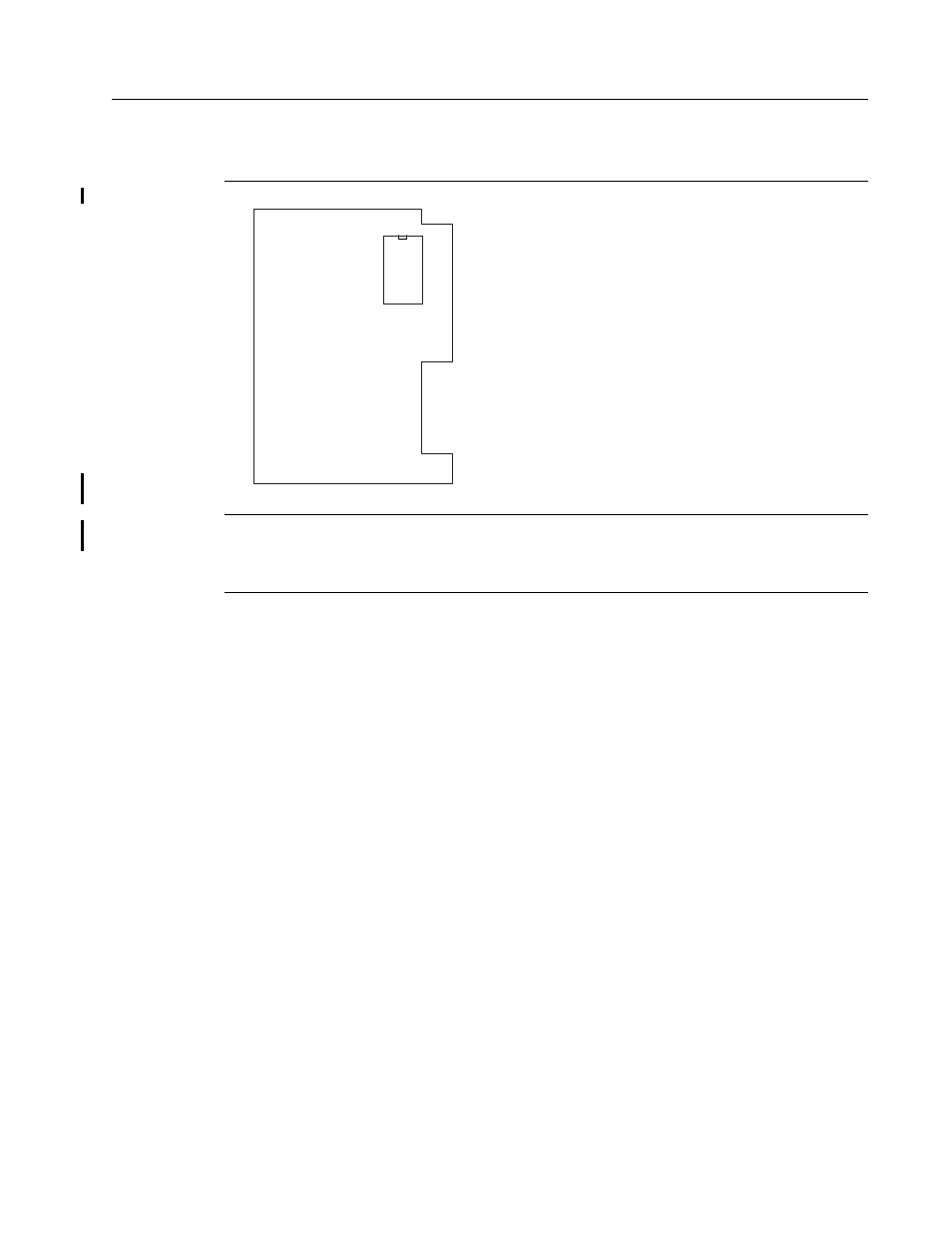
See the figure at the left for the location of the
communication plug PROM.
Series D and earlier
PLC-5/40C, -5/60C, or -5/80C processor
Remove the phillips head screw near the channel 1B LED
and gently remove the channel 1 communication plug. Be
aware that the memory grounding clip may move or drop off
from the cover mounting tab.
U18
PROM
1785-L11, -5/20 board
41024