Setting the input filter jumpers – Rockwell Automation 1771-IQ16 DC (24V) Isolated Input Module Installation Instructions User Manual
Page 4
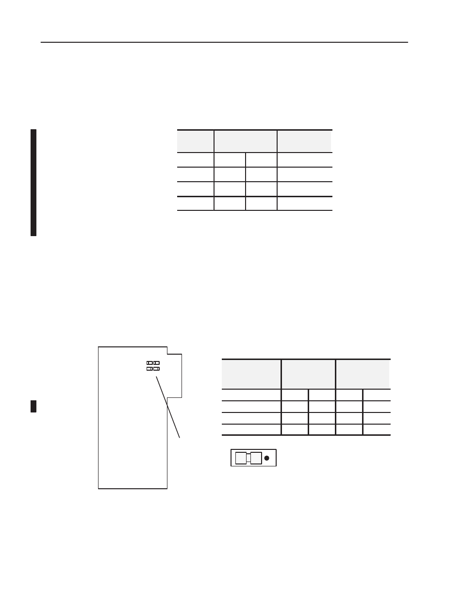
JPR1
JPR2
Filter Time Jumpers
JPR1 and JPR2 = Jumper for inputs 00 through 07
JPR3 and JPR4 = Jumper for inputs 10 through 17
JPR3
JPR4
0
1
0 1 0 1
0 1 0 1
Jumper in 0 position
10561-I
DC (24V) Isolated Input Module
4
Publication 1771-5.25 - November 1999
This module has four user-selectable filter time jumpers. Jumpers
JPR1 and JPR2 are used for filter times on inputs 00 through 07, and
jumpers JPR3 and JPR4 set filter times for inputs 10 through 17. The
jumper sets provide four different filter times as shown below.
Table B
Minimum and Maximum Filter Times
Filter Time
(ms)
Onto Off (ms)
Minimum Maximum
Off to On
0
0
0.56
µ
s
200
µ
s Typical
0.57
0.56
0.62
0.52 to 0.59ms
9.0
7.6
9.0
0.52 to 1.65ms
18.0
15.0
18.0
0.52 to 2.8ms
These filter times apply when the input is cycling from ON to OFF.
The OFF to ON filter time is fixed at 0.57ms.
To set the filtering time constant, proceed as follows:
1. Remove the side covers from the module circuit board by
removing the four screws securing the covers to the module and
remove the circuit board.
2. Position the jumpers as required to provide the filter time
constant you require.. Use your fingers to pull the jumper up and
position it on the two pins corresponding to your selection
(0 or 1).
Time Constant
(ms)
Inputs 00-07
Set Jumpers
JPR1 JPR2
Inputs 10-17
Set Jumpers
JPR3 JPR4
0
0
0
0
0
0.57 (factory default)
1
0
1
0
9.0
0
1
0
1
18.0
1
1
1
1
3. Reinstall the covers on the module circuit board and secure with
four screws.
Setting the Input Filter
Jumpers