Rockwell Automation 1771-IQ16 DC (24V) Isolated Input Module Installation Instructions User Manual
Dc (24v) isolated input module, Installation instructions
Publication 1771-5.25 - November 1999
DC (24V)
Isolated Input Module
Cat. No. 1771-IQ16 Series C
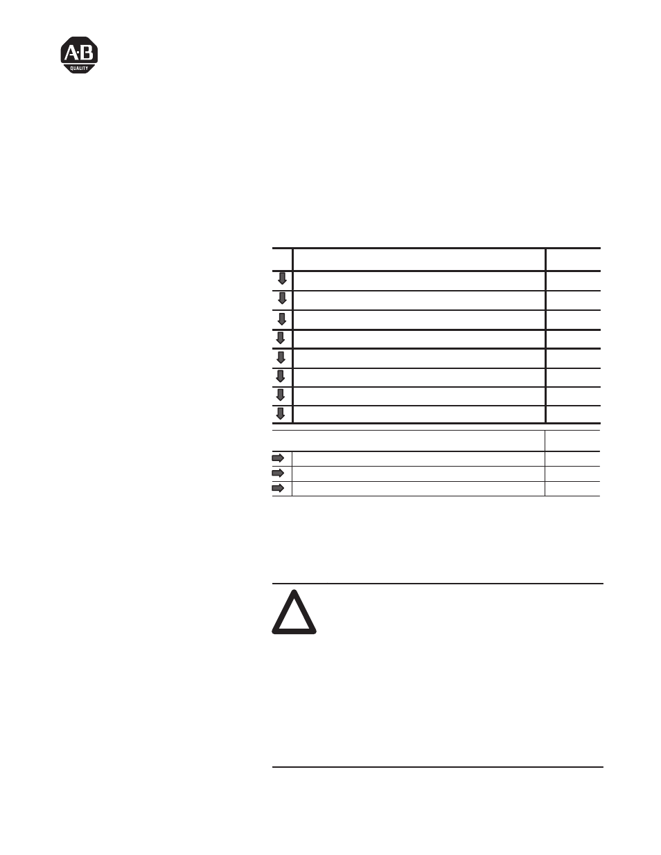
This document provides information on:
To:
See Page:
Prevent Electrostatic Damage
1
PreInstallation Information
2
Understand compliance to European Union directives
3
Calculate power requirements
3
Set the input filter jumpers
4
Key the backplane connector
5
Install the module and field wiring arm
5
Connect the wiring to the module
6
For this reference information
See page
Interpret the Status Indicators
9
CSA Hazardous Location
11
Specifications
12
The dc isolated input module is shipped in static-shielded packaging
to guard against electrostatic discharge damage. Observe the
following precautions when handling the module.
Electrostatic Discharge Damage
!
ATTENTION: Electrostatic discharge can damage
integrated circuits or semiconductors if you touch
backplane connector pins. Follow these guidelines
when you handle the module:
•
Touch a grounded object to discharge static potential
•
Wear an approved wrist-strap grounding device
•
Do not touch the backplane connector or
connector pins
•
Do not touch circuit components inside the module
•
If available, use a static-safe work station
•
When not in use, keep the module in its original
static-shielded packaging
Installation Instructions
To The Installer
Prevent Electrostatic
Damage
Document Outline
- 1771-5.25, DC (24V) Isolated Input Module, Installation Instructions
- To The Installer
- Prevent Electrostatic Damage
- Pre-Installation Considerations
- European Union Directive Compliance
- Power Supply Requirements
- Setting the Input Filter Jumpers
- Key the Backplane Connector
- Install the Module and Field Wiring Arm
- Connecting Wiring to the Module
- Interpreting the Status Indicators
- Specifications
- Back Cover