Connecting to the ethernet port, Interpreting the status indicators – Rockwell Automation 1752-L24BBBE SmartGuard 600 Controllers Installation User Manual
Page 17
SmartGuard 600 Controllers 17
Publication 1752-IN001C-EN-P - January 2009
Connecting to the Ethernet Port
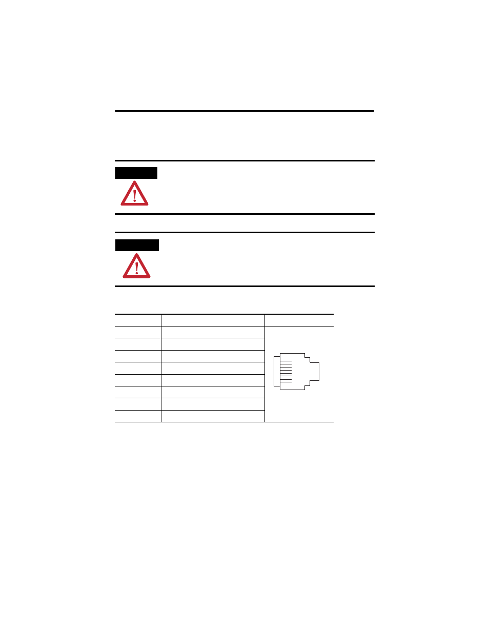
Use an RJ45 connector to connect the controller to the EtherNet/IP network.
Interpreting the Status Indicators
The SmartGuard 600 controller features status indicators for module, DeviceNet and
EtherNet/IP network status, lock, USB and EtherNet/IP communication, individual
input and output status, as well as an alphanumeric status display for DeviceNet
error codes, DeviceNet node address, and EtherNet/IP address information.
ATTENTION
The cable length must be less then 100 m (328 ft) between hub and nodes.
WARNING
If you connect or disconnect the Ethernet cable with power applied to this controller or any
other device on this network, an electrical arc can occur. This could cause an explosion in
hazardous location installations. Be sure that power is removed or the area is
nonhazardous before proceeding.
Ethernet Pin Placement
Pin No.
Pin Name
Pin Placement
8
Not used
7
Not used
6
RD-
5
Not used
4
Not used
3
RD+
2
TD-
1
TD+
8
1