Configure your input module, Configure your output module, Specifications – Rockwell Automation 1794-IV32_OV32 FLEX I/O Digital Sourcing Input and Sinking Output Modules User Manual
Page 3: Table 1, Input filter times, O:010, Octal
FLEX I/O Digital Sourcing Input and Sinking Output Modules 3
Publication 1794-IN122A-EN-P - June 2008
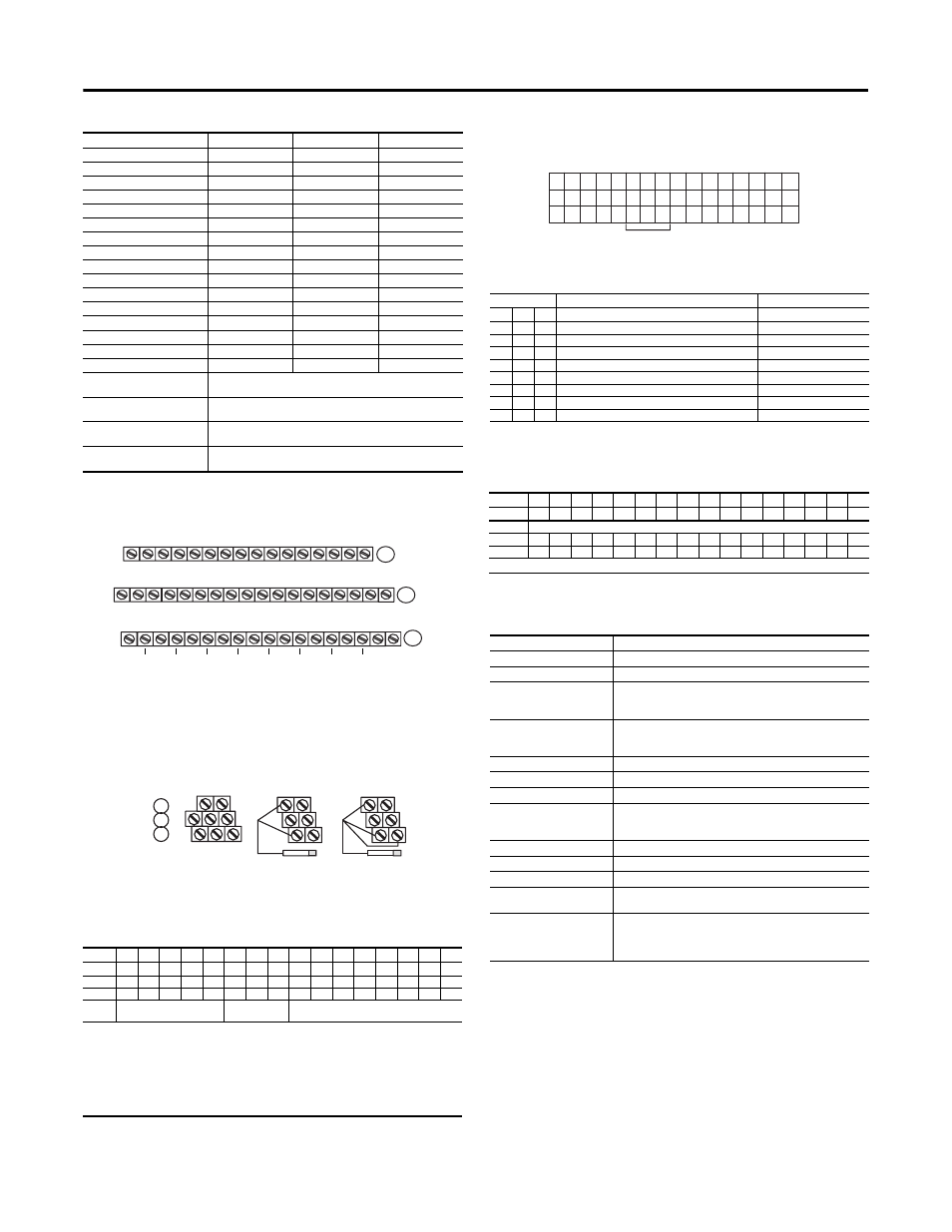
1794-TB32 and -TB32S for 1794-IV32, 1794-OV32
2 and 3-Wire Input Wiring for 1794-IV32
Configure Your Input Module
You configure your input module by setting bits in the configuration word (word 3).
Set the Input Filter Time for the 1794-IV32
To set the input filter time, set the associated bits in the output image
(complementary word) for the module.
Input Filter Times
Configure Your Output Module
You configure your output module by setting bits in the configuration word
(word 3)
Specifications
Table 1 Wiring Connections for 1794-IV32, 1794-OV32
Channel
Signal
Channel
Signal
0
A-0
16
B-17
1
A-1
17
B-18
2
A-2
18
B-19
3
A-3
19
B-20
4
A-4
20
B-21
5
A-5
21
B-22
6
A-6
22
B-23
7
A-7
23
B-24
8
A-8
24
B-25
9
A-9
25
B-26
10
A-10
26
B-27
11
A-11
27
B-28
12
A-12
28
B-29
13
A-13
29
B-30
14
A-14
30
B-31
15
A-15
31
B-32
+V1 dc power (inputs 0...15)
Power terminals 35, 37, 39 and 41 for inputs 0...15.
+V1 connected to terminals 35, 37, 39 and 41
COM1 dc Return (inputs 0...15)
Common terminals 36, 38, 40 and 42 for inputs 0...15.
V1 Return connected to terminals 36, 38, 40 and 42
+V2 dc power
(1)
(inputs IN16-IN31) Power terminals 43, 45, 47 and 49 for inputs 16...31.
+V2 connected to terminals 43, 45, 47 and 49
COM2 dc return (inputs IN16-IN31) Common terminals 44, 46, 48 and 50 for inputs 16...31.
V2 Return connected to terminals 44, 46, 48 and 50
(1)
2-wire input devices use signal and return terminals
3-wire devices use signal, return and supply terminals.
Dec
15
14
13
12
11
10
9
8
7
6
5
4
3
2
1
0
Oct
17
16
15
14
13
12
11
10
7
6
5
4
3
2
1
0
Read 1
I15
I14
I13
I12
I11
I10
I9
I8
I7
I6
I5
I4
I3
I2
I1
I0
Read 2
I31
I30
I29
I28
I27
I26
I25
I24
I23
I22
I21
I20
I19
I18
I17
I16
Write 1
Not used
Input Filter FT
0...31
Not used
Where I = Input
C = Counter value for input 15
FT = Input filter time
CR = Counter Reset
CF = Counter Fast - where 1 = Fast input (raw) data; 0 = Standard input filtered data
NU = Not used
Note: C, CR and CF not available when used with any series 1794-ASB or -ASB2 Remote I/O Adapters.
0 1 2 3 4 5 6 7 8 9 10 11 12 13 14 15
A
(1794-TB32 shown)
16 17 18 19 20 21 22 23 24 25 26 27 28 29 30 31 32 33
NC
B
NC
16 17 18 19 20 21 22 23 24 25 26 27 28 29 30 31 32 33
Inputs/Outputs - Channels 00-15
34 35 36 37 38 39 40 41 42 43 44 45 46 47 48 49 50 51
NC COM1 COM1 COM1 COM1 COM2 COM2 COM2 COM2 NC
C
Inputs/Outputs - Channels 16-31
+V1 +V1 +V1 +V1 +V2 +V2 +V2 +V2
+V1 = Terminals 35, 37, 39 and 41
+V2 = Terminals 43, 45, 47 and 49
COM1 = Terminals 36, 38, 40 and 42
COM2 = Terminals 44, 46, 48 and 50
NC = No connections (terminals 16, 33, 34 and 51)
0 -15
34-51
16-33
A
B
C
2-Wire Device
(Sinking Output)
0
1
0
1
3-Wire Device
(Sinking Output)
0
16
34
Bits
Description
Selected Filter Time
10
09
08
Filter Time for inputs 00...31
Off to On/On to Off
0
0
0
Filter Time 0 (Default)
0.25ms
0
0
1
Filter Time 1
0.50ms
0
1
0
Filter Time 2
1ms
0
1
1
Filter Time 3
2ms
1
0
0
Filter Time 4
4ms
1
0
1
Filter Time 5
8ms
1
1
0
Filter Time 6
16ms
1
1
1
Filter Time 7
32ms
Dec
15
14
13
12
11
10
9
8
7
6
5
4
3
2
1
0
Oct
17
16
15
14
13
12
11
10
7
6
5
4
3
2
1
0
Read 0
Not used
Write 1
O15
014
013
012
011
010
O9
O8
O7
O6
O5
O4
O3
O2
O1
O0
Write 2
O31
O30
O29
028
O27
O26
O25
O24
O23
O22
O21
O20
O19
O18
O17
O16
Where O = Output
Specifications - 1794-IV32 Flex I/O Digital Sourcing Input Module
Specification
Description
Number of I/O channels
32 (2 groups of 16), nonisolated within groups, sourcing
Module location
Cat. No. 1794-TB32, -TB32S
On-state voltage
19.2V dc minimum
24V dc nominal
31.2V dc maximum
On-state current
2.0 mA minimum
4.1mA nominal @ 24V dc
6.0mA maximum
Off-state voltage
5.0V dc maximum
Off-state current
1.5mA minimum
Input impedance
6.0K ohms maximum
Isolation voltage
50V (continuous), Basic Insulation Type
Type tested at 707V dc for 60 s, between field side and system
No isolation between individual channels
Flexbus current
40mA
Power dissipation
6W maximum @ 31.2V dc
Thermal dissipation
Maximum 20.5 BTU/hr @ 31.2V dc
Indicators (field side indication,
customer device driven)
32 yellow status indicators
Input filter time
(1)
Off to On
On to Off
(1)
Input off-to-on filter time is the time from a valid input signal to recognition by the module.
Input on-to-off filter time is time from the input signal dropping below the valid level to recognition by the module.
0.25ms, 0.5ms, 1ms, 2ms, 4ms, 8ms, 16ms, 32ms
0.25ms, 0.5ms, 1ms, 2ms, 4ms, 8ms, 16ms, 32ms
O:010
11 10 07 06 05 04 03 02 01 00
17 16 15 14 13 12
Octal
09 08 07 06 05 04 03 02 01 00
15 14 13 12 11 10
FT = 00...31
Dec.