Install your digital module, Connect wiring for the 1794-ov32 – Rockwell Automation 1794-IV32_OV32 FLEX I/O Digital Sourcing Input and Sinking Output Modules User Manual
Page 2
2 FLEX I/O Digital Sourcing Input and Sinking Output Modules
Publication 1794-IN122A-EN-P - June 2008
Install Your Digital Module
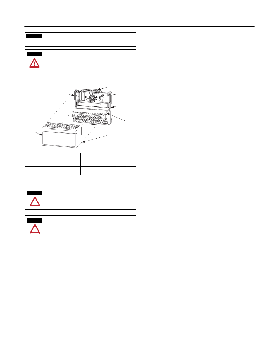
The module mounts on a 1794 terminal base.
1. Rotate the keyswitch (1) on the terminal base (2) clockwise to position 2 as
required for this type of module.
2. Make certain the flexbus connector (3) is pushed all the way to the left to
connect with the neighboring terminal base/adapter.
You cannot install the module unless the connector is fully extended.
3. Make sure the pins on the bottom of the module are straight so they will
align properly with the connector in the terminal base.
4. Position the module (4) with its alignment bar (5) aligned with the groove
(6) on the terminal base.
5. Press firmly and evenly to seat the module in the terminal base unit. The
module is seated when the latching mechanism (7) is locked into the
module.
Connect Wiring for the 1794-IV32
(using a 1794-TB32 or -TB32S Terminal Base)
1. Connect individual input wiring (0...15) to numbered terminals on the 0-15
row (A) as indicated in Table 1.
2. Connect the associated power to the +V1 terminal (35, 37, 39 or 41) on
the 34-51 row (C) as indicated in Table 1.
3. Connect the associated common for inputs 0...15 to COM1 (terminal 36,
38, 40 or 42) on the 34-51 row (C) as indicated in Table 1.
4. Connect individual input wiring (16...31) to numbered terminals on the
16-33 row (B) as indicated in Table 1.
Do not connect to terminals 16 or 33.
5. Connect the associated power to the +V2 terminal (43, 45, 47 or 49) on
the 34-51 row (C) as indicated in Table 1.
6. Connect the associated common for inputs 16...31 to COM2 (terminal 44
46, 48 or 50) on the 34-51 row (C).
7. If continuing input wiring power for inputs 0...15 to the next terminal base,
connect a jumper from terminal 41 (+V1) on this terminal base unit to the
power terminal on the next terminal base unit.
8. If continuing input wiring for inputs 0...15 common to the next terminal
base, connect a jumper from terminal 42 (COM1) on this terminal base
unit to the common terminal on the next terminal base unit.
9. If continuing input wiring power for inputs 16...31 to the next terminal
base, connect a jumper from terminal 49 (+V2) on this terminal base unit
to the power terminal on the next terminal base unit.
10. If continuing input wiring 16...31 common to the next terminal base,
connect a jumper from terminal 50 (COM2) on this terminal base unit to
the common terminal on the next terminal base unit.
Connect Wiring for the 1794-OV32
1. Connect individual output wiring (0 to 15) to numbered terminals on the
0-15 row (A) as indicated in Table 1.
2. Connect the associated power to the +V1 terminal (35, 37, 39 or 41) on
the 34-51 row (C) as indicated in Table 1.
3. Connect the associated output common (-V1) for outputs 0...15 to COM1
(terminal 36, 38, 40 or 42) on the 34 to 51 row (C).
4. Connect individual output wiring (16 to 31) to numbered terminals on the
16-33 row (B) as indicated in Table 1.
5. Connect the associated power to the +V2 terminal (43, 45, 47 or 49) on
the 34-51 row (C) as indicated in Table 1.
6. Connect the associated output common (-V2) for outputs 16...31 to
COM2 (terminals 44, 46, 48 or 50) on the 34-51 row (C).
7. If continuing power to the next terminal base, connect a jumper from
terminal 35, 37, 39 or 41 (+V1) and 43, 45, 47 or 49 (+V2) on this base
unit to the power terminal on the next base unit.
8. If continuing output common return to the next base unit, connect a
jumper from terminal 36, 38, 40 or 42 (COM1) and 44, 46, 48 or 50
(COM2) on this base unit to common on the next base unit (refer to the
installation instructions for the next type of terminal base unit).
IMPORTANT
To comply with North American restrictions, all connected I/O must be
powered from a source compliant with the following:
Class 2
WARNING
If you connect or disconnect wiring while the field-side power is on, an
electrical arc can occur. This could cause an explosion in hazardous
location installations. Be sure that power is removed or the area is
nonhazardous before proceeding.
Description
Description
1
Keyswitch
5
Alignment bar
2
Terminal base
6
Groove
3
Flexbus connector
7
Latching mechanism
4
Module
ATTENTION
During mounting of all devices, be sure that all debris (metal chips, wire
strands, etc.) is kept from falling into the module. Debris that falls into the
module could cause damage on power up.
ATTENTION
Do not remove or replace a Terminal Base unit when power is applied.
Interruption of the backplane can result in unintentional operation or
machine motion.
1
2
3
4
5
6
7