Synchlink overview, About the synchlink bypass switch block – Rockwell Automation 1751-SLBP SynchLink Bypass Switch Block Installation Instructions User Manual
Page 4
4 SynchLink Bypass Switch Block
Publication 1751-IN003B-EN-P - September 2001
SynchLink Overview
We designed the SynchLink system to provide the synchronization and coordination
of drive and motion control applications that are based on ControlLogix
and
PowerFlex 700s
stations.
About the SynchLink Bypass Switch Block
Use the SynchLink bypass switch block in SynchLink daisy-chain configuration
where a station, or group of stations, needs to be temporarily disconnected from
the SynchLink system without physical re-configuration of the cable system. The
bypass switch block is DIN rail-mounted and is housed in a two-piece plastic
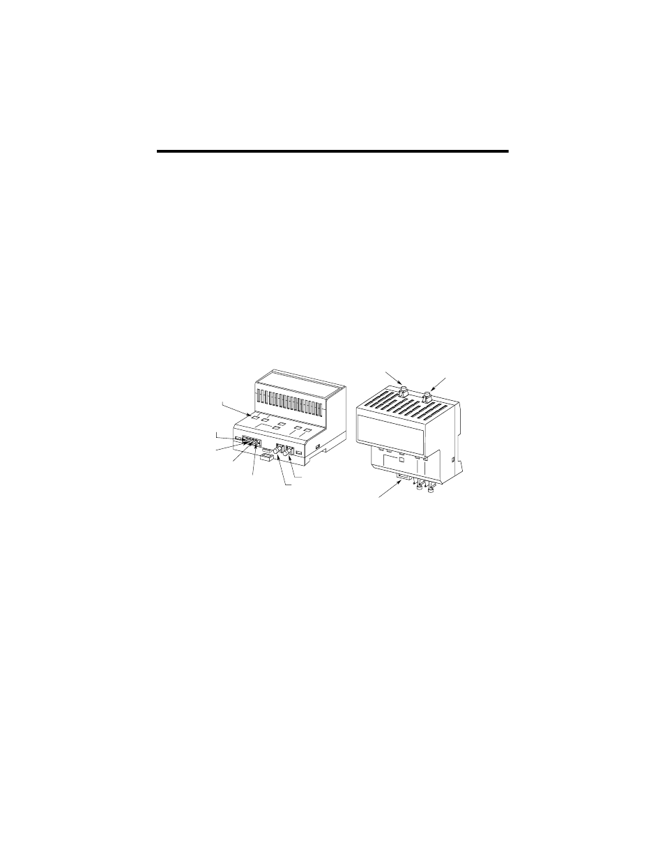
enclosure. Figure 1 identifies the components of the bypass switch block.
Figure 1 - Components of the bypass switch block
The bypass switch block has two modes of operation, pass-through and bypass.
The operational mode is determined by the state of the 24V dc digital input that is
driven by the local SynchLink station.
The pass-through mode is entered when the digital input is ON. In this mode,
optical signals from the upstream station are received at the receiver port RxIN1
and retransmitted to the local station via the transmitter port TxOUT2. Optical
signals generated by the local station are received at the receiver port RxIN2 and
retransmitted to the downstream station via the transmitter port TxOUT1. There is
no re-timing or signal regeneration in this mode.
The bypass mode is entered when the digital input is OFF. In this mode, signals
received from the upstream station at the port RxIN1 are converted to electrical
signals, re-timed, and retransmitted to the downstream station via the port TxOUT1.
The bypass switch block has no capabilities to detect or correct communication
error conditions that may exist during the course of pass-through or bypass
operation. The bypass switch block has no ability to report any abnormal
conditions to the local station.
Indicators
+24V dc
(pin 4)
+24V dc
Common (pin 3)
+24V dc Digital
Input (pin 2)
+24V dc
Common Digital
Input (pin 1)
RxIN1
TxOUT1
Din Rail Lock Tab
RxIN2
TxOUT2
31223-M