Connect wiring to the module – Rockwell Automation 1771-OD AC (120V) Isolated Output Module Installation Instructions User Manual
Page 8
AC (120V) Isolated Output Module
8
Publication 1771-IN078A-EN-P - October 2002
You make connections to the module through the 1771-WD field
wiring arm shipped with the module. The arm pivots on the chassis
to connect with the 8 terminals on the front of the module. The
wiring arm allows the module to be removed from the chassis
without disconnecting wiring.
1. Make certain all power is removed from the module before
making wiring connections.
2. Swing the wiring arm up into position on the front of the module.
The locking tab on the module will secure it into place.
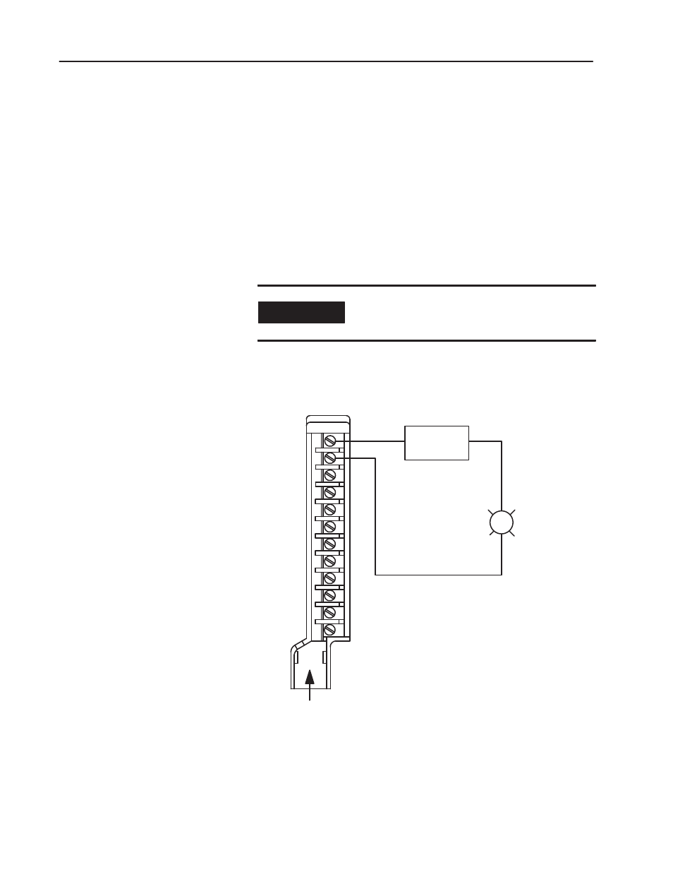
3. Make your connections to the field wiring arm as shown in
Figure 1. (Use the label on the front of the wiring arm to identify
your wiring.)
IMPORTANT
The field wiring arm terminal identification
number is not the same as the number of the bit
which controls that output.
You should identify the labels on the wiring arm with the name or
number of the device connected at each terminal.
Figure 1
Connection Diagram for the 1771ĆOD Isolated Output Module
L2
L1
(Actual wiring runs in this direction.)
11884-I
1
2
3
4
5
6
7
8
9
10
11
12
Load
120V ac Supply
Output 1B
Output 1A
Output 0B
Output 0A
Output 2A
Output 2B
Output 3A
Output 3B
Output 4A
Output 4B
Output 5A
Output 5B
If multiple power sources are used, do not exceed the specified isolation voltage.
Connect Wiring to the
Module