Rockwell Automation 1771-OD AC (120V) Isolated Output Module Installation Instructions User Manual
Page 10
AC (120V) Isolated Output Module
10
Publication 1771-IN078A-EN-P - October 2002
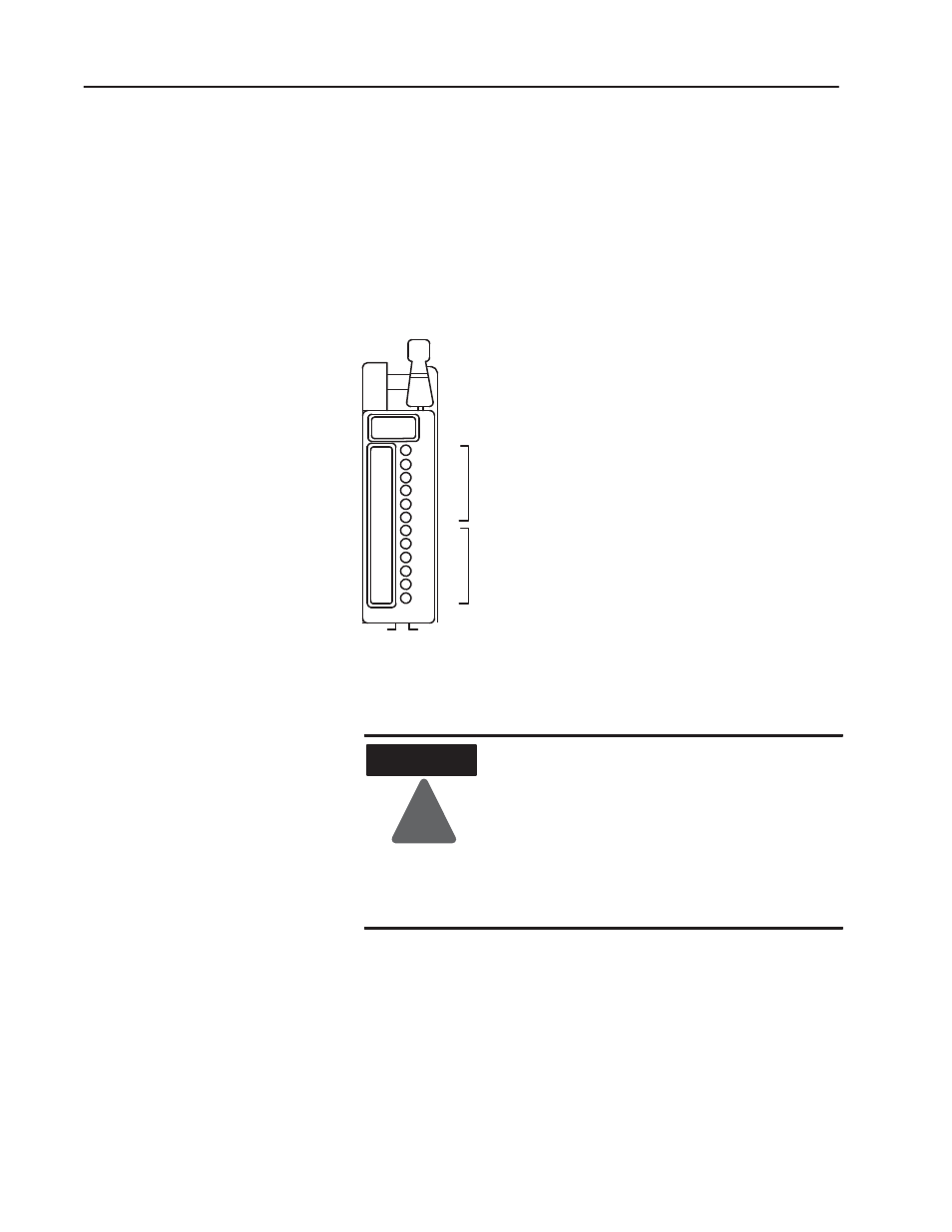
The module has 12 status indicators (Figure 3). The top 6 indicators
show the state of each output and are driven by the logic circuitry on
the programmable controller side of the module. These indicators
light when their corresponding outputs are energized.
The bottom 6 indicators display a blown–fuse condition at the
respective output regardless of the state of the output. This indicator
is driven by your field device power supply.
Figure 3
Status Indicators
11886-IA
00
01
02
03
04
05
00
01
02
03
04
05
Red Output
Status Indicators
Clear FuseĆBlown
Status Indicators
Each module output is individually fused. You can easily access the
module fuse by removing the front component-side cover.
ATTENTION
!
Remove power from the 1771 I/O chassis
backplane and wiring arm before removing or
installing the module.
•
Failure to remove power from the backplane or
field wiring arm could cause module damage,
degradation of performance, or injury.
•
Failure to remove power from the backplane
could cause injury or equipment damage due to
possible unexpected operation.
If a blown fuse occurs:
1. Turn off power to the I/O chassis backplane.
2. Pivot the wiring arm away from the module and pull the module
from the I/O chassis.
3. Remove the front half of the protective cover from the unlabeled
side of the module by removing the two slotted screws.
Interpreting the Status
Indicators
Replacing a Fuse