Rockwell Automation 1772-LV,D17726.6.1 A and I MNL MINI-PLC-2/15 PROCESSO User Manual
Page 43
Assembly and Installation
Chapter 3
3Ć23
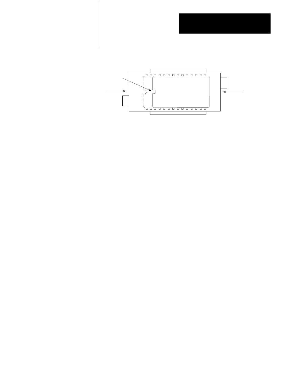
Figure 3.22
EPROM Installation
Release
Notch
Lock
OFF
ON
10128ĆI
24ĆPin EPROM
5. Line up the right side of the EPROM pin with the right side of the socket
and seat the EPROM in the socket.
6. Lock the EPROM in place by pushing the OFF tab toward the right.
7. Close the EPROM access door ad tighten the screw.
MiniĆPLCĆ2/15 Processor
The Mini PLC-2/15 Processor Module (Cat. No. 1771-LV) is inserted into the
left-most slot of the I/O Chassis (Figure 3.23). With the Mode Select Switch in
the PROG mode, slide the Processor Module onto the plastic tracks and push
firmly to seat it in the backplane sockets. once in position, snap down the
Module Locking Latch to secure the Mini-PLC-2/15 Processor.
Field Wiring Arms
Field Wiring Arms (Cat. No. 1771-WA) for each I/O Module slot are shipped
with the I/O Chassis. If a different Field Wiring Arm is required for a certain
Module, it is shipped with that Module.
The Field Wiring Arms snap onto the lower horizontal bar of the I/O Chassis
(Figure 3.24). When I/O Modules are in place, the Field Wiring Arms pivot up
and connect to the Module.
I/O Modules
The I/O Modules are inserted into their corresponding keyed slots by sliding
them onto the plastic tracks at the top and bottom of the slots (Figure 3.15). Do
not force the I/O Modules into their backplane sockets; rather, apply firm and
even pressure to seat them.
Note: If the I/O Module is a double-slot Module, it must occupy a complete
Module Group. Overlapping f Module Groups is not permitted.