Input block wiring diagram, See the figures for wiring information – Rockwell Automation 1790D-XXXX DeviceNet Digital Base D-Shell Module CompactBlock LDX I/O Series B User Manual
Page 11
DeviceNet Digital Base D-shell Block CompactBlock LDX I/O 11
Publication
1790-IN013A-EN-P - September 2006
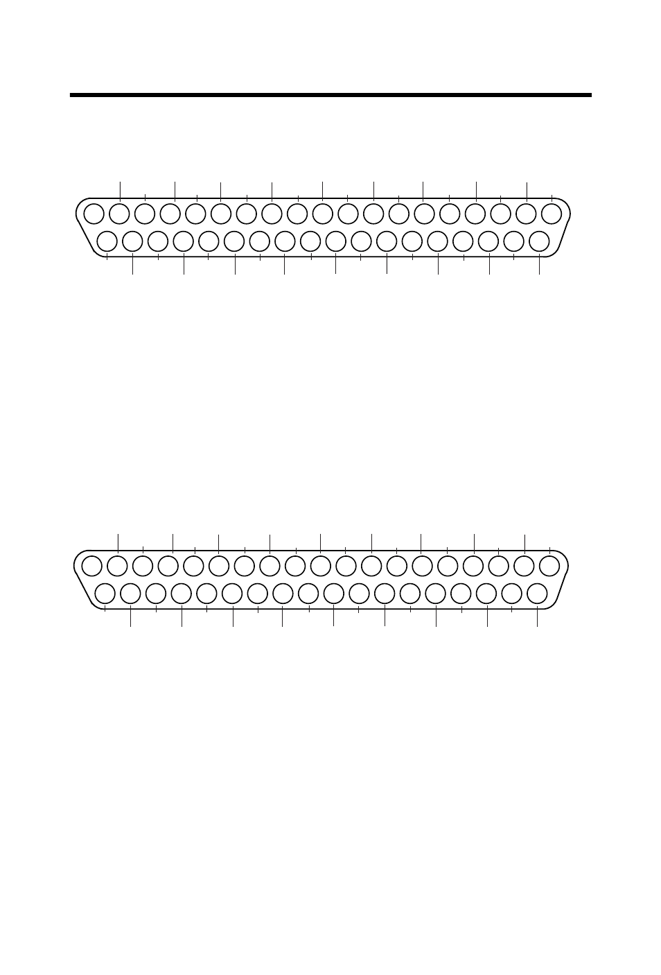
See the figures for wiring information.
1790D-16BVO
Input Block Wiring Diagram
For inputs 0…7: For sinking inputs, wire Com 1 to Field Power (+) 24V dc and Com 0 to Field
Power (-) GND. For sourcing inputs, wire Com 1 to Field Power (-) GND and Com 0 to Field
Power (+) 24V dc.
For inputs 8…15: For sinking inputs, wire Com 3 to Field Power (+) 24V dc and Com 2 to Field
Power (-) GND. For sourcing inputs, wire Com 3 to Field Power (-) GND and Com 2 to Field
Power (+) 24V dc.
Note that all Com 1 and Com 3 are internally connected. Com 1 is used for inputs 0…7.
Com 3 is used for inputs 8…15.
1790D-8BV8V Input/Output Wiring Diagram
For sinking inputs, wire Com 1 to Field Power (+) 24V dc and Com 0 to Field Power (-) GND.
For sourcing inputs, wire Com1 to Field Power (-) GND and Com 0 to Field Power (+) 24V dc.
Note that all Com 1 are internally connected.
For sinking outputs, wire Com 2 to Field Power (+) 24Vdc, and
Com 3 to Field Power (-) GND. Note that all Com 2 are internally connected.
44165
19
18
17
16
15
14
13
12
11
10
9
8
7
6
5
4
3
2
1
37
36
35
34
33
32
31
30
29
28
27
26
25
24
23
22
21
20
COM0
I0
I1
I2
I3
I4
I5
I6
I7
COM2
I8
I9
I10
I11
I12
I13
I14
I15
COM1
COM1
COM1
COM1
COM1
COM3
COM3
COM3
COM3
COM1
COM1
COM1
COM1
COM3
COM3
COM3
COM3
COM3
44166
19
18
17
16
15
14
13
12
11
10
9
8
7
6
5
4
3
2
1
37
36
35
34
33
32
31
30
29
28
27
26
25
24
23
22
21
20
COM0
I0
I1
I2
I3
I4
I5
I6
I7
COM2
I8
I9
I10
I11
I12
I13
I14
I15
COM1
COM1
COM1
COM1
COM1
COM3
COM3
COM3
COM3
COM1
COM1
COM1
COM1
COM3
COM3
COM3
COM3
COM3