6 - troubleshooting, Chapter objectives, Led indicators – Rockwell Automation 1791-IOBB USER MANUAL User Manual
Page 30: Troubleshooting
Chapter
6
6Ć1
Troubleshooting
In this chapter you will learn about the LED indicators on the block I/O
module, and how to use them to troubleshoot the unit.
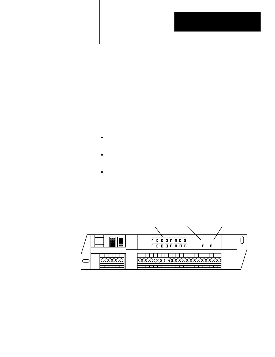
Each block I/O module has LED indicators (Figure 6.1) which provide
indication of specific functions. Each module has the following:
green communication indicator – indicates whether communication is
occurring between processor or scanner and the block.
red power indicator – indicates if power is applied to module and
internal hardware status
16 I/O status indicators (8 input–8 output or 10 input–6 output) – reflect
the state of the individual inputs and outputs (on or off)
The location of the indicators is shown in Figure 6.1. Refer to Table 6.A
for status indications reported by the indicators.
Figure 6.1
Indicators on the Block I/O Module (1791-IOBA shown)
OUTPUT
INPUT
COMM POWER
Communication LED (green) Power LED (red)
Status Indicators
10846-I
Chapter Objectives
LED Indicators