Rockwell Automation 1794-IB16XOB16P_IB10XOB6 Flex I/O Input/ Output Module Installation Instructions User Manual
Page 3
3
Publication 1794-IN083B-EN-P - November 2004
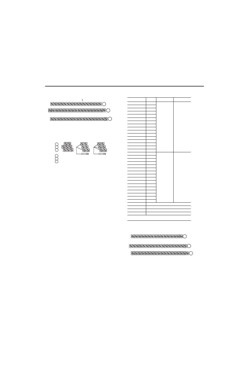
1794-TB3 and -TB3S Terminal Base Wiring for the
1794-IB10XOB6
2 and 3-Wire Input Wiring for 1794-IB10XOB6
Connecting Wiring for the 1794-IB16XOB16P
1. Connect individual input wiring (IN0 to IN15) to numbered terminals
on the 0-15 row (A) as indicated in the table below.
2. Connect the associated power to the +V1 terminal (35, 37, 39 or 41)
on the 34-51 row (C) as indicated in the table below.
3. Connect the associated common (-V1) for IN0 to IN15 to COM1
(terminal 36, 38, 40 or 42) on the 34-51 row (C).
4. Connect individual output wiring (OUT0 to OUT15) to terminals 17
thru 32 on the 16-33 row (B) as indicated in the table below. (Note:
Do not connect to terminals 16 or 33.)
5. Connect the associated power to the +V2 terminal (43, 45, 47 or 49)
on the 34-51 row (C) as indicated in the table below.
6. Connect the associated common (-V2) for OUT0 to OUT15 to
COM2 (terminal 44, 46, 48 or 50) on the 34-51 row (C).
7. If continuing input wiring to the next terminal base unit, connect a
jumper from terminal 41(+V1) to the power terminal on the next base
unit; connect a jumper from terminal 42 (COM1) to the common
terminal on the next base unit.
8. If continuing output wiring to the next terminal base unit, connect a
jumper from terminal 49 (+V2) to the power terminal on the next
base unit; connect a jumper from terminal 50 (COM2) to the common
terminal on the next base unit.
Wiring for 1794-IB16XOB16P (use with 1794-TB32 or -TB32S
terminal base unit)
1794-TB32 Terminal Base Wiring for the 1794-IB16XOB16P
17 18 19 20 21 22 23 24 25 26 27 28 29 30 31 32 33
0 1 2 3 4 5 6 7 8 9 10 11 12 13 14 15
16
35 36 37 38 39 40 41 42 43 44 45 46 47 48 49 50 51
34
Inputs
Commons
(1794-TB3 shown)
-V (Supply Common) = Terminals B-16 and B-33
+V (Supply +Voltage In) = Terminals C-34 and C-51
-V
Voltage
In +V
Voltage
Out +V
Voltage
A
B
C
(Use B-33 and C-51 for daisy-chaining to next terminal base unit)
Common
-V
Common
Outputs
?
??
??
A
B
C
0-15
16-33
34-51
= Sink Input
= Common
= +V dc
2-Wire Device
(Sourcing Output)
3-Wire Device
(Sourcing Output)
A
B
C
Input
Signal
Return
Supply
1
Input 0
A-0
V1 Return
connected to
terminals 36, 38,
40 and 42
+V1 connected to
terminals 35, 37,
39 and 41
Input 1
A-1
Input 2
A-2
Input 3
A-3
Input 4
A-4
Input 5
A-5
Input 6
A-6
Input 7
A-7
Input 8
A-8
Input 9
A-9
Input 10
A-10
Input 11
A-11
Input 12
A-12
Input 13
A-13
Input 14
A-14
Input 15
A-15
Output 0
B-17
V2 Return
connected to
terminals 44, 46,
48 and 50
+V2 connected to
terminals 43, 45,
47 and 49
Output 1
B-18
Output 2
B-19
Output 3
B-20
Output 4
B-21
Output 5
B-22
Output 6
B-23
Output 7
B-24
Output 8
B-25
Output 9
B-26
Output 10
B-27
Output 11
B-28
Output 12
B-29
Output 13
B-30
Output 14
B-31
Output 15
B-32
+V1 dc power
Power terminals 35, 37, 39 and 41
Com1 dc Return
Common terminals 36, 38, 40 and 42
+V2 dc power
Power terminals 43, 45, 47 and 49
Com2 dc Return
Common terminals 44, 46, 48 and 50
1
2-wire input devices use signal and supply terminals; 3-wire devices use signal, return
and supply terminals
17 18 19 20 21 22 23 24 25 26 27 28 29 30 31 32 33
IN0 IN 1 IN2 IN3 IN4 IN5 IN6 IN7 IN8 IN9 IN10 IN11 IN12 IN13 IN14 IN15
35 36 37 38 39 40 41 42 43 44 45 46 47 48 49 50 51
34
NC
+V2 = Terminals 43, 45, 47 and 49
Inputs
+V1 COM1 +V1 COM1 +V1 COM1 +V1 COM1 +V2 COM2 +V2 COM2 +V2 COM2 +V2 COM2
NC
+V1 = Terminals 35, 37, 39 and 41
COM1 = Terminals 36, 38, 40 and 42
NC = No connections (terminals 16, 33, 34 and 51)
COM2 = Terminals 44, 46, 48 and 50
NC
NC
(1794-TB32 shown)
Outputs
A
B
C
0 1 2 3 4 5 6 7 8 9 10 11 12 13 14 15
OUT0 OUT1 OUT2 OUT3 OUT4 OUT5 OUT6 OUT7 OUT8 OUT9 OUT10 OUT11 OUT12 OUT13 OUT14 OUT15