Rockwell Automation 1794-IB16XOB16P_IB10XOB6 Flex I/O Input/ Output Module Installation Instructions User Manual
Page 2
2
Publication 1794-IN083B-EN-P - November 2004
North American Hazardous Location Approval
The following modules are North American Hazardous Location approved:
1794-IB10XOB6 and 1794-IB16XOB16P.
Installing Your Digital Input/Output Module
The 1794-IB10XOB6 module mounts on a 1794-TB3 or -TB3S terminal base.
The 1794-IB16XOB16P module mounts on a 1794-TB32 or -TB32S terminal
base.
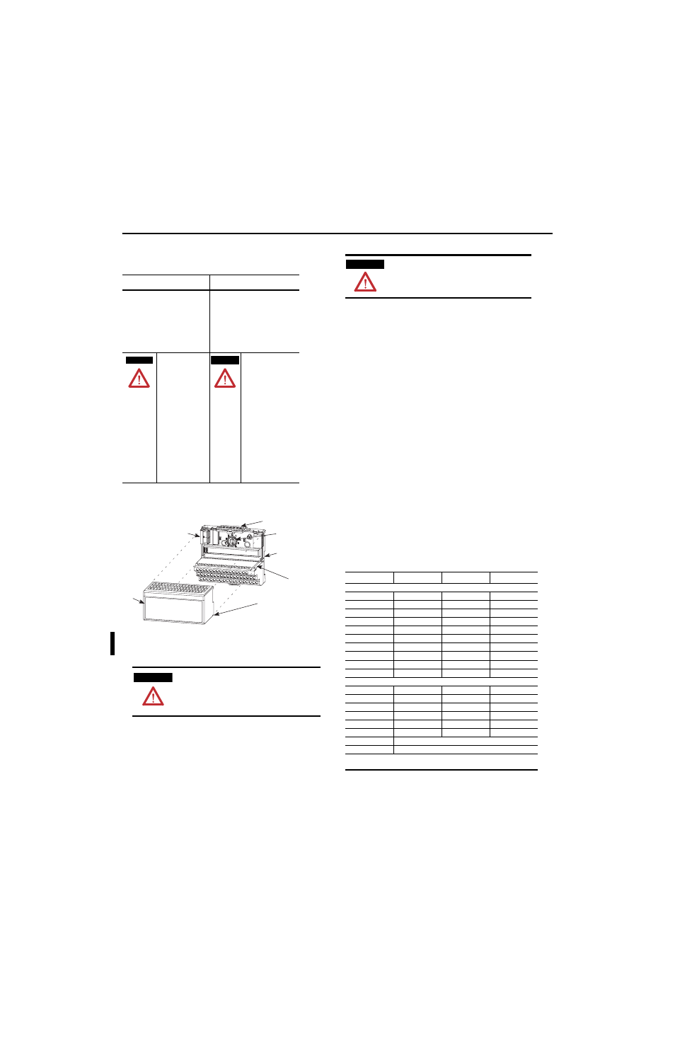
1. Rotate the keyswitch (1) on the terminal base (2) clockwise to position
2 as required for this type of module.
2. Make certain the flexbus connector (3) is pushed all the way to the left
to connect with the neighboring terminal base/adapter. You cannot
install the module unless the connector is fully extended.
3. Make sure the pins on the bottom of the module are straight so they
will align properly with the connector in the terminal base.
4. Position the module (4) with its alignment bar (5) aligned with the
groove (6) on the terminal base.
5. Press firmly and evenly to seat the module in the terminal base unit.
The module is seated when the latching mechanism (7) is locked into
the module.
Connecting Wiring for the 1794-IB10XOB6
1. Connect individual input and output wiring to numbered terminals on
the 0-15 row (A) as indicated in the table below.
2. Connect the associated +V dc power lead of the input device to the
corresponding terminal on the 34-51 row (C) for each input as
indicated in the table below. (The +V power terminals of row (C) are
internally connected together.)
3. Connect the associated input device common (3-wire devices only)
and output device common to the corresponding terminals on the
16-33 row. (B) for each input and output as indicated in the table
below. (Commons are internally connected together.)
4. Connect +V dc power to terminal 34 on the 34-51 row (C).
5. Connect dc common to terminal 16 on the 16-33 row (B).
6. If daisychaining power to the next terminal base, connect a jumper
from terminal 51 (+V dc) on this base unit to terminal 34 on the next
base unit.
7. If continuing dc common to the next base unit, connect a jumper
from terminal 33 (common) on this base unit to terminal 16 on the
next base unit.
Wiring Connections for the 1794-IB10XOB6
The following information applies when
operating this equipment in hazardous
locations:
Informations sur l’utilisation de cet équipement
en environnements dangereux :
Products marked “CL I, DIV 2, GP A, B, C, D” are
suitable for use in Class I Division 2 Groups A, B, C,
D, Hazardous Locations and nonhazardous locations
only. Each product is supplied with markings on the
rating nameplate indicating the hazardous location
temperature code. When combining products within
a system, the most adverse temperature code
(lowest “T” number) may be used to help determine
the overall temperature code of the system.
Combinations of equipment in your system are
subject to investigation by the local Authority
Having Jurisdiction at the time of installation.
Les produits marqués "CL I, DIV 2, GP A, B, C, D" ne
conviennent qu’à une utilisation en environnements
de Classe I Division 2 Groupes A, B, C, D dangereux et
non dangereux. Chaque produit est livré avec des
marquages sur sa plaque d’identification qui
indiquent le code de température pour les
environnements dangereux. Lorsque plusieurs
produits sont combinés dans un système, le code de
température le plus défavorable (code de température
le plus faible) peut être utilisé pour déterminer le
code de température global du système. Les
combinaisons d’équipements dans le système sont
sujettes à inspection par les autorités locales
qualifiées au moment de l’installation.
EXPLOSION HAZARD
• Do not disconnect
equipment unless power
has been removed or the
area is known to be
nonhazardous.
• Do not disconnect
connections to this
equipment unless power
has been removed or the
area is known to be
nonhazardous. Secure any
external connections that
mate to this equipment by
using screws, sliding
latches, threaded
connectors, or other means
provided with this product.
• Substitution of
components may impair
suitability for Class I,
Division 2.
• If this product contains
batteries, they must only be
changed in an area known
to be nonhazardous.
RISQUE D’EXPLOSION
• Couper le courant ou
s’assurer que l’environnement
est classé non dangereux avant
de débrancher l'équipement.
• Couper le courant ou
s'assurer que l’environnement
est classé non dangereux avant
de débrancher les connecteurs.
Fixer tous les connecteurs
externes reliés à cet
équipement à l'aide de vis,
loquets coulissants,
connecteurs filetés ou autres
moyens fournis avec ce produit.
• La substitution de
composants peut rendre cet
équipement inadapté à une
utilisation en environnement de
Classe I, Division 2.
• S’assurer que
l’environnement est classé non
dangereux avant de changer
les piles.
ATTENTION
During mounting of all devices, be sure that all
debris (metal chips, wire strands, etc.) is kept
from falling into the module. Debris that falls
into the module could cause damage on
power up.
WARNING
AVERTISSEMENT
1
2
3
4
5
6
7
WARNING
If you remove or insert the module while the
backplane power is on, an electrical arc can occur.
This could cause an explosion in hazardous location
installations. Be sure that power is removed or the
area is nonhazardous before proceeding..
Input
1
Signal
Return
Supply
Sink Input
Input 0
A-0
B-17
C-35
Input 1
A-1
B-18
C-36
Input 2
A-2
B-19
C-37
Input 3
A-3
B-20
C-38
Input 4
A-4
B-21
C-39
Input 5
A-5
B-22
C-40
Input 6
A-6
B-23
C-41
Input 7
A-7
B-24
C-42
Input 8
A-8
B-25
C-43
Input 9
A-9
B-26
C-44
Source Output
Output 0
A-10
B-27
Output 1
A-11
B-28
Output 2
A-12
B-29
Output 3
A-13
B-30
Output 4
A-14
B-31
Output 5
A-15
B-32
+V dc
C-34 thru C-51 (internally connected together)
Common
B-16 thru B-33 (internally connected together)
1
Two wire input devices use signal and supply terminals. Three wire devices use
signal, return and supply terminals.