Connect the wiring to the module – Rockwell Automation 1771-ID16GM Installation Instructions User Manual
Page 6
ac (120V) Isolated Input Module
6
Publication 1771-IN001A–EN–P – May 2000
17643
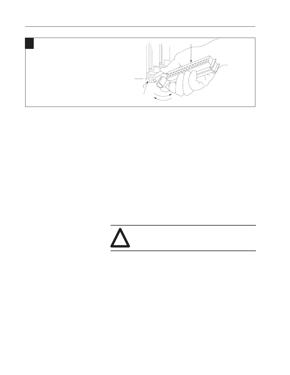
wiring arm
install
remove
horizontal bar
Attach the wiring arm (1771-WN) to the horizontal
bar at the bottom of the I/O chassis.
The wiring arm pivots upward and connects with
the module so you can install or remove the
module without disconnecting the wires.
1771-WN
2
Connections to the input module are made to the 40 terminal field
wiring arm (cat. no. 1771-WN) shipped with the module. Attach the
wiring arm to the pivot bar on the bottom of the I/O chassis. The
wiring arm pivots upward and connects with the module so you can
install or remove the module without disconnecting the wires.
1. Make certain all power is removed from the module before
making wiring connections.
2. Swing the wiring arm up into position on the front of the module.
The locking tab on the module will secure it into place.
3. Make your connections to the field wiring arm as shown in the
following figure. (Use the label on the front of the wiring arm to
identify your wiring.)
Note: A shorting bar may be used to connect the commons if
channel-to-channel isolation is not required.
!
ATTENTION: The field wiring arm terminal
identification number is not the same as the number of
the bit associated with that input.
Connect the Wiring to the
Module