Key the backplane connector, Install the module and field wiring arm – Rockwell Automation 1771-ID16GM Installation Instructions User Manual
Page 5
ac (120V) Isolated Input Module
5
Publication 1771-IN001A–EN–P – May 2000
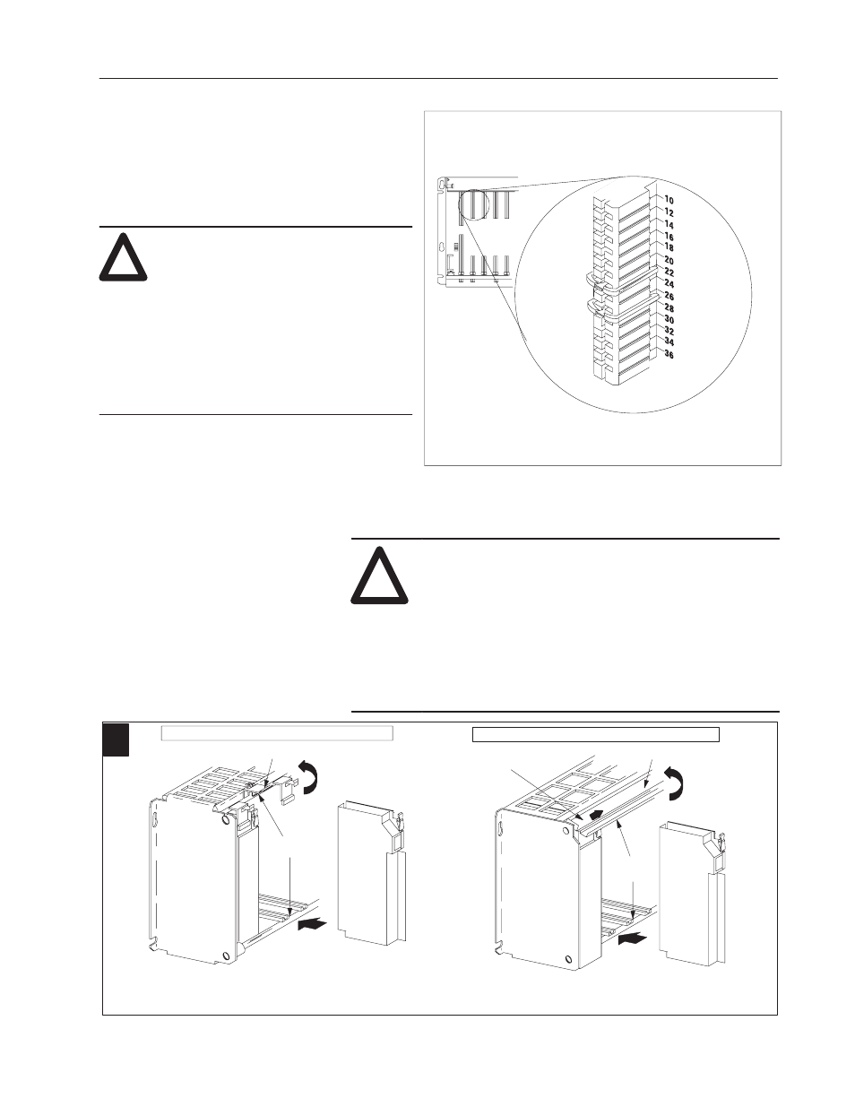
Key the Backplane Connector
Place your module in any slot in the chassis
except the leftmost slot which is reserved for
processors or adapters.
ATTENTION: Observe the following
precautions when inserting or removing
keys:
•
insert or remove keys with your fingers
•
make sure that key placement is correct
Incorrect keying or the use of a tool can
result in damage to the backplane
connector and possible system faults.
!
Position the keying bands in the backplane connectors to correspond to
the key slots on the module.
Place the keying bands:
between 22 and 24
between 26 and 28
You can change the position of these bands if
subsequent system design and rewiring makes
insertion of a different type of module necessary.
Upper Connector
11022-I
I/O chassis
!
ATTENTION: Remove power from the 1771 I/O
chassis backplane and field wiring arm before
removing or installing an I/O module.
•
Failure to remove power from the backplane or wir-
ing arm could cause module damage, degradation of
performance, or injury.
•
Failure to remove power from the backplane could
cause injury or equipment damage due to possible
unexpected operation.
Swing the chassis locking bar down into place to secure
the modules. Make sure the locking pins engage.
1771-A1B, -A2B, -A3B, -A3B1, -A4B I/O chassis
1771-A1B, -A2B, -A3B1, -A4B Series B I/O chassis
locking tab
card guides
Module
Module
19809
card guides
locking bar
locking bar pin
Snap the chassis latch over
the top of the module to secure it.
1
Install the Module and Field
Wiring Arm