Rockwell Automation 1771-IR Series D RTD Input Module User Manual User Manual
Page 19
2–5
Installing the RTD Input Module
Publication 1771Ć6.5.129 - March 2000
Channel
Terminal
Identification
1
18
C
17
B
16
A
2
15
C
14
B
13
A
3
12
C
11
B
10
A
4
9
C
8
B
7
A
5
6
C
5
B
4
A
6
3
C
2
B
1
A
Cable impedance –– Since the operating principle of the RTD
module is based on the measurement of resistance, you must take
special care in selecting your input cables. Select a cable that has a
consistent impedance throughout its entire length. We recommend
Belden 9533 or equivalent. As cable length is directly related to
overall cable impedance, keep input cables as short as possible by
locating your I/O chassis as near the RTD sensors as I/O module
considerations permit. Keep the cable free of kinks and nicks to the
shielding material.
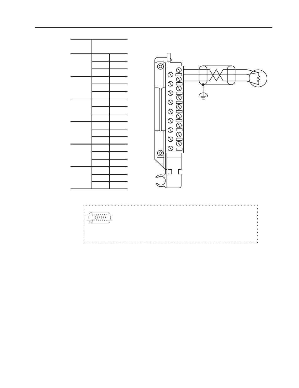
Connection Diagram for the RTD Input Module (1771ĆIR/D)
Field Wiring Arm
Cat. No. 1771ĆWF
18
17
16
1
15
14
13
12
11
10
9
8
7
6
5
4
3
2
11846ĆI
RTD
(Channel 1 shown)
Functional
Ground
The sensor cable must be shielded. The shield must:
•
extend the length of the cable, but be connected only at the 1771 I/O chassis
•
extend up to the point of termination
Important:
The shield should extend to the termination point, exposing just enough cable to
adequately terminate the inner conductors. Use heat shrink or another suitable
insulation where the wire exits the cable jacket.
Refer to Appendix E for 2-wire and
3-wire RTD connections.