Remove the protective caps – Rockwell Automation 1786-RPFRXL ControlNet Fiber Ring Modules Installation Instructions User Manual
Page 18
18 ControlNet Fiber-optic Ring Repeater Modules
Rockwell Automation Publication 1786-IN003D-EN-P - April 2011
9. Connect the fiber cable as described on
10. If you plan not to use a channel, attach a small section of fiber cable (or a
Simplex fiber loop) between the Receive port (RX) and the Transmit
Port (TX) of any unused fiber port to create a jumper.
Although not required for module operation, the jumper turns the
status indicators green and prevents the relay contact connector from
opening and indicating a failure.
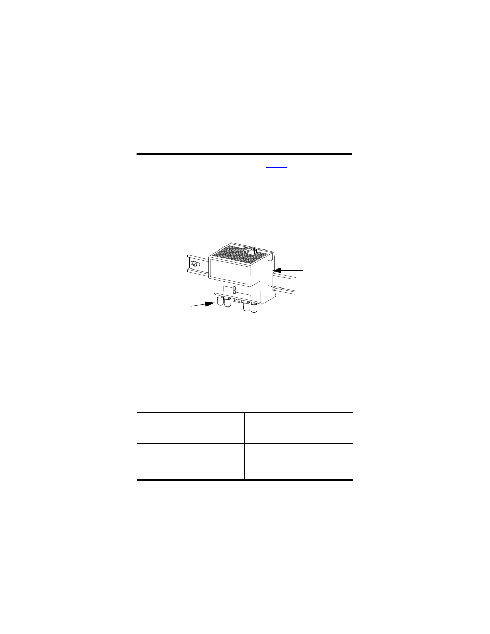
Remove the Protective Caps
1. Remove the protective caps from the fiber ports that you are going to
use.
2. Save the caps for future use.
The left side of the module (not shown here) also contains a
backplane connector.
If you plan
Then
To place the module in storage
Keep the protective caps on the channels to
protect the unit from dust.
To connect another module to the right
backplane connector
Remove the protective backplane cap and
save the cap for future use.
Not to connect to the right backplane
connector
Leave the backplane cap on.
Protective
Backplane Cap
Protective Cap