Rockwell Automation 1606-XLS960 DC Power Supply User Manual
Page 5
10000172266
01
M. GUELMI
7-19-13
5
6
B
TECHNICAL DATA SHEET
BUL. 1606-XLS960EE, 1606-XLS960FE
POWER SUPPLIES
1606-XLS960: Power Supply Instruction Manual
1606-XLS960: Bedienungsanleitung für Stromversorgung
Remote Control of Output Voltage
(see Fig. 6)
The shut-down input can also be used to remotely adjust the output voltage. A control voltage
applied on the shut-down input reduces the adjusted output voltage
Instructions:
1. Set the unit into “Single Use” mode
2. Set the output voltage adjustment to the maximum desired voltage.
3. Apply a control voltage to reduce the output voltage
Externe Steuerung der Ausgangsspannung
(siehe Bild 6)
Mithilfe einer externen Steuerspannung am Shut-down Eingang kann die eingestellte
Ausgangsspannung in gewissen Grenzen reduziert werden.
Anleitung:
1. Gerät in „Single Use“ Modus stellen
2. Ausgangsspannung mittels Potentiometer auf den maximal gewünschten Wert einstellen
3. Steuerspannung am Shut-down Eingang anlegen um die Ausgangsspannung zu reduzieren
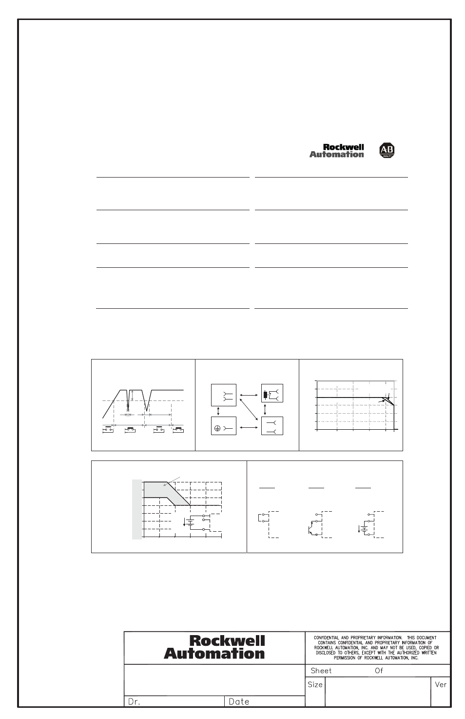
DC-OK Relay Contact
(see Fig. 3)
This feature monitors the output voltage, which is produced by the power supply, and is
independent of a return voltage from a unit which is connected in parallel.
Contact closes when the output voltage is above 90% of the adjusted value.
Contact opens when the output voltage is typ. below 90% of the adjusted value. Short dips will
be extended to a length of 250ms. Dips shorter than 1ms will be ignored.
Contact ratings: max.: 60Vdc 0.3A, 30Vdc 1A, 30Vac 0.5A, resistive load, min. current 1mA
DC-OK Relais Kontakt
(siehe Bild 3)
Diese Funktion überwacht die vom Gerät erzeugte Ausgangsspannung und lässt sich von einer
rückwärts eingespeisten Spannung nicht beeinflussen (z.B.: bei Parallelschaltung)
Kontakt schließt, wenn die Ausgangsspannung typ. höher als 90% des eingestellten Wertes ist.
Kontakt öffnet, wenn die Ausgangsspannung typ. kleiner als 90% des eingestellten Wertes ist.
Kurze Einbrüche werden auf 250ms verlängert. Einbrüche kürzer 1ms werden ignoriert.
Kontakt Belastbarkeit: max.: 60Vdc 0.3A, 30Vdc 1A, 30Vac 0.5A, (R-Last), min. Strom 1mA
Shut-down Input
(see Fig. 7)
This feature allows a switch-off of the power supply with a control switch or an external voltage.
The shut-down function has no safety feature included. The shut-down occurs immediately while
the turn-on is delayed by 350ms. In a shut-down condition, the output voltage is <2V and the
output power is <0.5W.
„Shut-down“ Eingang
(siehe Bild 7)
Abschaltung des Gerätes durch einen Signalschalter oder eine Fremdspannung. Die Abschaltung
beinhaltet keine Sicherheitsfunktionen. Die Abschaltung erfolgt unverzögert, das
Wiedereinschalten mit einer Verzögerung von ca. 350ms. Im abgeschaltetem Zustand ist die
Ausgangsspannung <2V und die Ausgangsleistung <0,5W.
Single Use / Parallel Use Selector
This selector on the front of the unit enables a load sharing when power supplies are connected in
parallel. The “Parallel Use” mode regulates the output voltage in such a manner that the voltage at
no load is approx. 4% higher than at nominal load.
If no jumper is plugged in, the unit is also in “Single Use”. Factory setting is “Single Use”.
Instructions for parallel use:
The output voltage shall be adjusted to the same value (±100mV) in “Single Use” at the same load
condition on all units, or shall be left with the factory settings. Afterwards, the jumper on the front
of the unit shall be moved from “Single Use” to “Parallel Use”
„Single Use“ / „Parallel Use“ Steckbrücke
Diese Steckbrücke an der Frontseite des Geräts ermöglicht eine Lastaufteilung, wenn mehrere
Geräte parallel geschaltet sind. In „Parallel Use“ Modus ist die Ausgangsspannung so geregelt,
dass diese im Leerlauf um etwa 4% höher ist als bei Nennlast.
Ein nicht eingesteckter Jumper bedeutet auch „Single Use“. Werkseinstellung ist „Single Use“.
Anleitung für Parallelbetrieb:
Die Ausgangsspannung aller Geräte bei gleicher Belastung in „Single Use“ auf ±100mV genau
einstellen oder in Werkseinstellung belassen. Danach die Steckbrücke an der Front des Gerätes
von „Single Use“ auf „Parallel Use“ umstecken.
Fig. 3 / Bild 3
DC-OK-Signal
Fig. 4 / Bild 4
Insulation / Isolation, typ.
Fig. 5 / Bild 5
Output derating / Leistungsrücknahme
250ms
90%
V
ADJ
<
1ms
10%
open
V
OUT
= V
ADJ
open
closed
closed
>
1ms
A
D
C
B
B
Input
DC-ok
Earth
Output
-
+/-
Shut-down
N
L
Fig. 6 / Bild 6
Remote Control of Output Voltage / Externe Steuerung der Ausgangsspannung
Fig. 7 / Bild 7
Shut-down Input / Eingang
Control Voltage
14V
2V
4V
6V
16V
18V
20V
28V
22V
24V
26V
8V
10V
12V
24V
Unit
28V
32V
36V
40V
56V
44V
48V
52V
48V
Unit
Adjustment range
Output Voltage
15
16
Control
Voltage
Shut-
down
Input
-
+
n.c.
OFF: linked /
verbunden
ON : open / offen
Option A:
OFF: I > 0.3mA
ON : I < 0.1mA
Option B:
(open collector)
OFF: U < 1V
ON : U = 4 -29V
Option C:
(ext. voltage /
ext. Spannung)
15
16
Shut-
down
Input
-
I
n.c.
15
16
Shut-
down
Input
15
16
Shut-
down
Input
-
+
U
n.c.
Allowed Output Power
0
-25
0
20
40
70°C
240W
480W
720W
960W
1200W
1440W
60
Ambient Temperature
85Vac
*)
90 to 276Vac
*)
or 170 to 276Vac
continuous
short-term (4s)
*) only 1606-XLS960E, 1606-XLS960F